Samiflex Coupling
5 ปีที่ผ่านมา
Samiflex®
Coupling - Power transmissionsELASTIC COUPLINGS
SAMIFLEX ELASTOMERIC COUPLINGS
TAP Part Engineering Co., Ltd.Company in Thailand
Contact us: tap.part@engineer.com
Mobile: 091-4844332

Samiflex® A0, INTERNAL ELASTIC COUPLING
Samiflex® A1, INTERNAL ELASTIC COUPLING AND RING

Samiflex® A2 SP, COMPLETE COUPLING
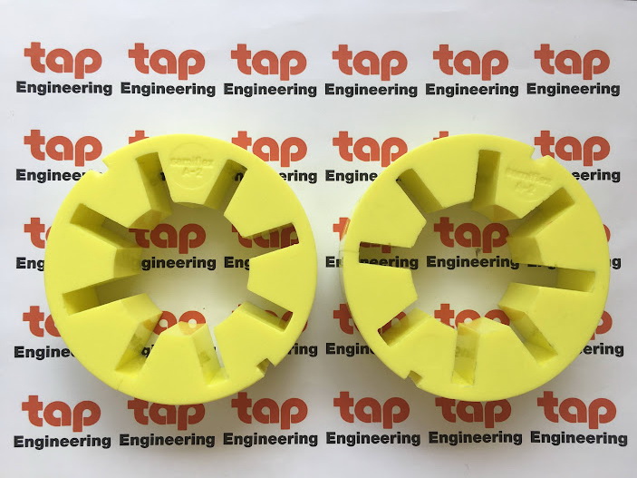
Samiflex® A2, INTERNAL ELASTIC COUPLING


Samiflex® A3B HT PB Coupling (Complete Set)

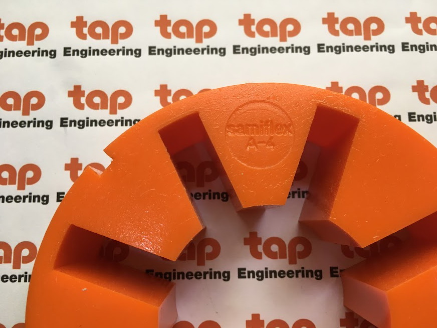
Samiflex® A4 Coupling + Ring + Insert


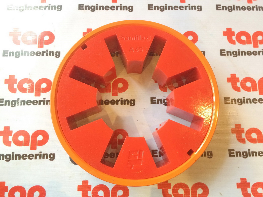
Samiflex® A45 Coupling Complete (Pilot Bore)
with HDT (Red) insert


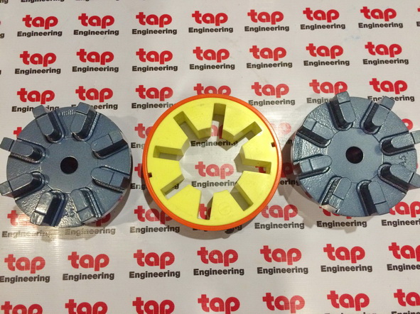
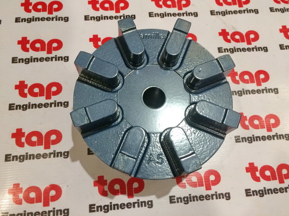
Samiflex® Complete A5


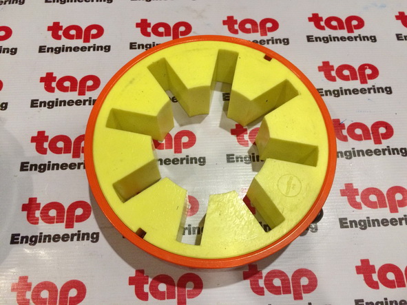
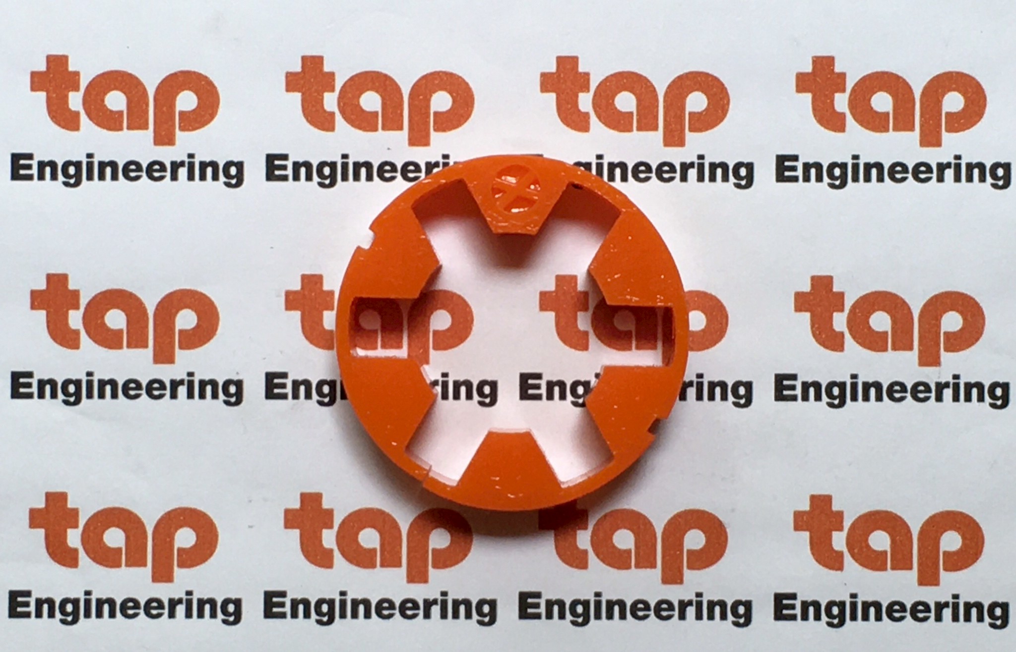
Yellow = standard in Type A (95 shore A)
Blue = standard in Spacer couplings Type CS (80 shore A)
Brown = Optional, HD, +30% (97 shore A)
ต้องการสอบถามราคา รายละเอียดสินค้า กรุณาแจ้งยี่ห้อ รุ่น จำนวน เข้ามาที่
Mobile: 091-484-4332
Email: tap.part@engineer.com
Email: tap.part@engineer.com
SAMIFLEX
ELASTIC COUPLINGS
SAMIFLEX ELASTOMERIC COUPLINGS
Now there's a new solution to one of the most costly and troublesome problems facing maintenance
personnel - coupling failure and the expensive down time associated with fixing it.
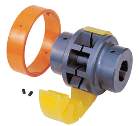
Only four parts to the Samiflex Coupling
The two identical hubs (items A & B) are manufactured in cast
iron, cast steel or aluminium alloy and incorporate four, six
or eight teeth, depending on size rating of the coupling.
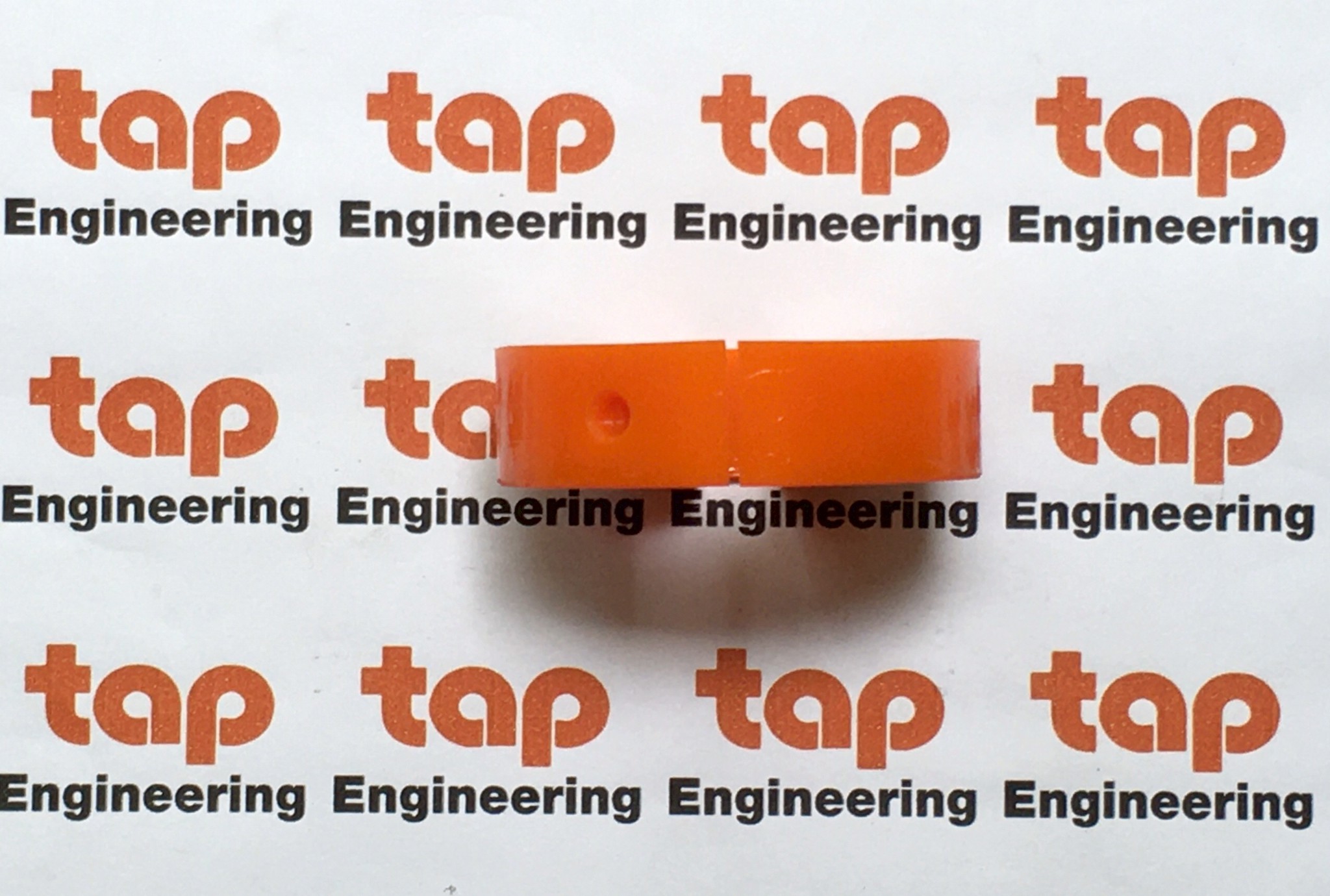
A precision cast and machined polyurethane insert (item C) fits
between the hubs and is split axially so fitting and removal can
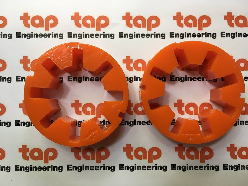
be achieved without moving hubs.The holding ring,
manufactured in steel, polyamide or bronze (item D) is fitted
over the insert securing both insert and ring between hubs.
The coupling requires no bolts or nuts.
ATEX Approval
The range of Samiflex Couplings has been approved under ATEX
directive 94/9/EC - for use in potentially explosive atmospheres.
Features and Benefits
• Coupling insert removable without the need to remove
either driving or driven equipment.
• Change out of coupling insert is faster than
any other coupling.
• No lubrication or maintenance required over the life
of the insert.
• The polyurethane insert can be supplied in a variety of
hardnesses to optimise torque capacity and damping.
• Polyurethane insert is very resistant to chemical attack.
• Standard insert can handle large temperature range
from -40 to 80 °C.
• High temperature insert available up to 150 °C.
• Hubs can be rotated independently during motor test.
• No metal to metal contact
• Large bore to torque capacity
• Vertical operation possible with standard coupling.
• Retaining rings provided with locking screws as standard.
The specification contained within this brochure are correct at time of going
to print. Autogard are continually reviewing and updating the specifications
on all its product range and therefore reserve the right to change any detail.
Assembly & Disassembly
Once hubs (A) and (B) and holding ring (D) have been installed
and aligned on the shafts the coupling hubs will not have to be
moved again during the life of the equipment.The elastic insert
(C) can then be installed between the parallel slots formed by
the hub teeth.
With the insert in position, slide the retaining ring (D) into
position over the polyurethane insert. Centrifugal force will
expand the insert under operation ensuring a tight, secure fit
inside the retaining ring.
Removing and replacing the coupling insert is very simple and
requires no special tools. By removing the retaining ring, the
insert can be quickly and easily removed and replaced without
the need to undo screws, bolts or other fasteners.
B
D
C
A
1
Electric Motor, Steam Engine,
Load Characteristics Steam Turbine Water Turbine, 6 Cyl. Recip. Engine 4 Cyl. Recip. Engine
Gas Turbine 8 Cyl. Recip. Engine
Constant Torque
eg. Centrifugal pumps, compressors & 1.0 1.5 2.0 2.5
blowers, light duty agitators and fans.
Slight Fluctuations
eg. Slurry pumps, Screw compressors, 1.5 2.0 2.5 3.0
Lobe and Vane Blowers.
Moderate Fluctuations and/or
Slight Shock Loads 2.0 2.5 3.0 3.5
Double acting pumps, Recip. Comp.
Large Fluctuations and/or
Moderate Shock Loads 2.5 3.0 3.5 4.0
1 or 2 Cylinder Recip.pumps.
Shock Loads or
Light Torque Reversals 3.0 3.5 4.0 Consult Factory
Slitters, Rod Mill, Hot Mill
Heavy Shock Loads or
Large Torque Reversals Consult Factory Consult Factory Consult Factory Consult Factory
Feed Rolls, Reversing Mills
(1) Use a minimum Service Factor of 1.25 when driving through a gearbox or using a direct on-line electric motor.
(2) Consult Autogard when using a reciprocating engine with fewer than 4 cylinders.
(3) Service Factors provided are for reference only. Customer experience may dictate the selection of different service factors.
Coupling Selection
SAMIFLEX THE ELASTIC INSERT
Method
Data required for Coupling Selection.
• Application details (for service factor)
• Kilowatt and rpm of the driver.
• Shaft details of the driving and driven equipment.
(1) Determine the service factor (SF) from the application and
classification lists noted below.
(2) Calculate the maximum Kw/1000 rpm rating:
Kw/1000 rpm = (Kw x 1000 x SF) / rpm
Select the coupling which has a higher max rating.
(3) Compare the maximum rpm capacity & bore requirements
to the catalogue limits for the coupling selected.
Example
Driver: Water Turbine (75 Kw at 1500 rpm)
Driven equipment: Screw Compressor
Turbine Bore: 60 mm Compressor Bore: 50 mm
Distance Between Shaft Ends: 140 mm
Service Factor for the Water Turbine & Screw Compressor: SF = 2
Kw/1000 rpm = (75 Kw x 1000 x 2) / 1500
Kw/1000 rpm = 100
Coupling selection based on max rating: A4B
Coupling Bore Capacity: 75 mm
Maximum Speed for the A4B is 3275 rpm unbalanced.
DBSE for the A4B Type SP is 140 mm
The A4B Type SP is acceptable in this application.
Service Factors - SF
The Samiflex elastic insert is manufactured from a special blend of polyurethane compound manufactured
to best meet the demanding characteristics of a high performance elastic coupling.
Samiflex elastic inserts are offered in three styles of compound and four hardness ratings allowing the most appropriate insert to be
selected for the application.
The standard elastic insert is supplied at 95 shore and is a yellow colour. High performance inserts type HD and HDT are coloured
ochre and red respectively and enable Samiflex torque ratings to be increased by 40% (consult factory).
Insert Ref. Hardness Colour Temp. Rating
80 Shore A Clear
Standard STD 90 Shore A Blue -40 / 80 C
95 Shore A Yellow
High Temp. HT 95 Shore A Orange -40 / 140 C
HD 97 Shore A Ochre -40 / 80 C
High
Performance HDT 97 Shore A Red -40 / 140 C
2
Coupling Type A0 A1 A2 A3 A3B A4 A4B A45 A5 A5B A55 A6 A7 A8 A9 A10 A11 A12
Max. Bore d1 24 38 44 50 58 65 70 75 85 95 95 110 130 150 180 210 210 300
Pilot Bore 8 14 17 19 19 24 24 25 29 29 30 39 48 63 73 96 96 100
D1 65 83 111 144 144 182 182 202 225 225 250 265 306 363 425 523 503 710
D2 52 65 80 85 105 110 140 125 140 160 155 180 205 242 280 330 350 500
D3 52 65 86 116 116 150 150 170 190 190 215 233 267 326 385 483 458 650
d2 32 39 45 52 52 70 70 90 89 89 115 112 135 157 188 218 216 380
G 73 91 127 156 156 180 180 198 216 216 246 260 310 382 420 482 512 709
L 28 34 47 56 56 63 63 70 77 77 90 95 116 147 162 188 190 250
Standard "DBSE" 17 23 33 44 44 54 54 58 62 62 66 70 78 88 95 106 132 209
Dist. Between Hubs "E" 1.5 1.5 2.5 2.5 2.5 3.5 3.5 3.5 3.5 3.5 3.5 3.5 4 5 5 6 6 5
H – – 55 65 65 85 85 93 101 101 109 119 134 154 162 192 216 359
J – – 36 45 45 47 47 52 57 57 68 70 88 114 129 145 148 175
K 16 22 32 42 42 51 51 56 59 59 64 67 75 85 92 102 128 210
Dimensions
(mm)
Coupling Type A0 A1 A2 A3 A3B A4 A4B A45 A5 A5B A55 A6 A7 A8 A9 A10 A11 A12
Maximum KW per 1000 6 14 29 58 58 120 120 211 301 301 361 482 963 1806 2880 4607 6157 20942
Max. Cont.Torque Nm 55 138 275 550 550 1150 1150 2013 2875 2875 3450 4600 9200 17250 27500 44000 58800 200000
Maximum KW per 1000 - - - - - 162 162 283 406 406 487 649 1298 2346 3743 5990 8000 -
Max. Cont.Torque Nm - - - - - 1550 1550 2700 3875 3875 4650 6200 12400 22400 35750 57200 76400 -
Max. Speed - Unbal. 11000 8800 6500 4900 4900 3800 3800 3300 3000 3000 2650 2450 2100 1750 1450 1175 1250 875
Max. Speed - Bal. (Steel) 14650 11750 8850 6500 6500 5000 5000 4475 4000 4000 3550 3250 2850 2345 1985 1580 1650 1175
Moment of Inertia (Kg-m2) – 0.0012 0.005 0.012 0.020 0.050 0.075 0.102 0.155 0.210 0.275 0.437 0.825 2.326 4.95 12 16 52
Weight (Kg) 1 1.8 3.8 6.2 8.5 12.5 16 19 26 31 36 47 75 137 218 350 410 1000
Axial Tolerance +0.3 +0.5 +0.5 +0.7 +0.7 +0.8 +0.8 +1.0 +1.0 +1.0 +1.0 +1.0 +1.0 +1.5 +1.5 +2.0 +2.0 +3.0
Radial / Parallel 0.30 0.30 0.50 0.50 0.50 0.70 0.70 0.70 0.70 0.70 0.80 0.80 1.00 1.00 1.00 1.50 1.50 0.6
Angular Tolerance 2 2 2 2 2 1.3 1.3 1.3 1.3 1.3 1.3 1.3 1 1 1 1 1 0.7
1) STD Inserts will be supplied as standard unless specified. High Torque (HD), High Temperature (HT) or High Torque & Temperature (HDT) Inserts can be supplied upon request.
2) Maximum unbalanced speeds are based on Cast Iron Hubs. Higher speeds may be attained using Ductile Iron or Steel Hubs - Consult Autogard
3) Distance Between Shaft ends (DBSE) is based on the shafts mating flush with the end of the hub face. Shorter or longershaft separations may be obtained by overhanging the shaft or hub
4) Weights and inertias are based on solid hubs.
5) Peak torque is 2 x maximum continuous torque.
G
J H J
L
K
L
E
D3
D1
D2
d1
d2
Technical Details and Dimensions
SAMIFLEX COUPLING TYPE A
STD & HT
Insert
HD & HDT
Insert
Technical
data
Displacement
values
3
1) Refer to bush manufacturers for recommended torque capacity of each bush.
G
L
M
D3
D1
D2
E
b
t
Ød
G
L
E
D3
D1
D2
SAMIFLEX COUPLING FOR TAPER BUSH
45 48 50 55 60 65 70 75 80 85 90 95 100
14 14 14 16 18 18 20 20 22 22 25 25 28
3.8 3.8 3.8 4.3 4.4 4.4 4.9 4.9 5.4 5.4 5.4 5.4 6.4
* * *
* * * * *
* * * * * * * *
* * * * * * * * * * *
* * * * * * * * * * * * * * *
Coupling Taper Bore Range Dimensions
Size Bush min. max. L G E D1 D2 D3 M
A1 -TB/TBI 1108 9 28 27 77 1.5 83 65 65 29
A2 -TB/TBI 1210 11 32 32 97 2.5 111 80 86 38
A3 -TB/TBI 1610 14 42 32 107 2.5 144 85 116 38
A4 -TB/TBI 2012 14 50 38 130 3.5 182 110 150 42
A45 -TB/TBI 2517 16 60 50 158 3.5 202 125 170 50
A5 -TB/TBI 3020 25 75 56 173 3.5 225 160 190 55
A6 -TB 3535 35 90 95 259 3.5 265 180 233 67
A7 -TB 4040 40 100 120 318 4 306 205 267 70
Samiflex Coupling Bored to Suit Taper Lock Bushings
Type TBI Type TB
Dimensions - Taper Bushes
d 9 10 11 12 14 16 18 19 20 22 24 25 28 30 32 35 38 40 42
b 3 3 4 4 5 5 6 6 6 6 8 8 8 8 10 10 10 12 12
t 1.4 1.4 1.8 1.8 2.3 2.3 2.8 2.8 2.8 2.8 3.3 3.3 3.3 3.3 3.3 3.3 3.3 3.3 3.3
1108 * * * * * * * * * * * * *
1210 * * * * * * * * * * * * *
1610 * * * * * * * * * * * * * * *
2012 * * * * * * * * * * * * * * *
2517 * * * * * * * * * * * * * *
3020 * * * * * * * *
3535 * * * *
4040
4
SAMIFLEX SPACER COUPLING - TYPE DO
SAMIFLEX SPACER COUPLING - TYPE SP
E
L C L
D3
D2
D1
d1
D3
D2
D1
e E
L L3
d2
D5
D4
d1
L2 C L1
Coupling
Maximum KW Max Max
Dimensions
Size
per 1000 RPM Bore
RPM
STD Insert (d1) D1 D2 D3 L C (D.B.S.E.)
A2D 26 42 4100 111 60 86 60 100 120 140
A3D 52 60 4100 144 88 116 70 100 120 140 180
A4D 104 80 3600 182 110 150 85 120 140 180
A45D 184 90 3100 202 125 170 95 120 140 180
Note - The Samiflex Drop Out Spacer (Type DO) is interchangeable with many competitive Drop-out couplings - Consult Autogard
1) L = C - 1
2) Refer to Page 4 for dimensions D2 and E.
Coupling Max Range Max Dimensions
Size d1 d2 RPM D1 D3 D4 D5 L1 L2 L3 e C (DBSE)
A1-SP 38 42 5500 83 65 100 67 34 45 45 2 100 120 140
A2-SP 42 48 5000 111 86 120 83 47 62 62 2 100 120 140
A3B-SP 55 65 4500 144 116 140 107 56 76 76 2.5 100 120 140
A4B-SP 75 85 3500 182 150 178 140 63 88 88 2.5 120 140 180
A45-SP 75 90 3100 202 170 200 150 70 97 97 2.5 120 140 180
A5B-SP 95 110 2900 225 190 225 179 77 106 106 2.5 140 180 200
A55-SP 95 110 2600 250 215 245 180 90 121 121 3 140 180 200
A6-SP 110 120 2500 265 233 265 198 95 128 128 3 180 200 250
5 A7-SP 130 130 2200 306 267 290 230 116 153 153 3 200 250 280
SAMIFLEX COUPLING FOR SAE FLYWHEEL ARRANGEMENTS
SAMIFLEX LIMITED END FLOAT COUPLING - TYPE FX
E L
D3
D1
D
B.C.D.
D2
G
T
F
X
INSERT
G
E
L L
D3
D2
D1
d1
1) For standard flywheel dimensions (D, B.C.D. and hole sizes) - Consult Autogard
2) Flywheels are available in non-standard sizes - Consult Autogard.
Coupling Max SAE J620 Dimensions
Size Bore Number
D1 D2 D3 E G L T
A2 EB-SAE 54.0 6-1/2", 7-1/2", 8" 111 80 86 2.5 100 46 12
A3B EB-SAE 69.8 7-1/2", 8", 10" 144 105 116 2.5 124 56 15
A4B EB-SAE 95.2 8", 10", 11-1/2" 182 135 150 3.5 144 63 17
A5B EB-SAE 114.3 10", 11-1/2", 14" 225 160 190 3.5 168 76 20
A6 EB-SAE 114.3 11-1/2", 14", 16" 265 180 234 3.5 196 94 22
A7 EB-SAE 139.7 14", 16", 18" 306 205 267 4 229 115 25
A8 EB-SAE 150 16", 18", 21" 363 240 326 5 280 146 30
Coupling Max Dimensions Axial
Size Bore
D1 D2 D3 D.B.S.E. E G L F X
Float
(d1)
A4B FX 95.2 182 135 150 54 3.5 180 63 11.5 12.5 1
A4.5 FX 82.5 202 125 170 58 3.5 198 70 11.5 12.5 1
A5B FX 114.3 225 160 190 62 3.5 216 77 14.5 16 1.5
A55 FX 101.6 250 155 215 66 3.5 246 90 14.5 16 1.5
A6 FX 114.3 265 180 233 70 3.5 260 95 18.5 20.5 2
A7 FX 139.7 306 205 267 78 4 310 116 18.5 20.5 2
A8 FX 150 363 242 326 88 5 382 147 21 24 3
A9 FX 180 425 280 385 96 5 420 162 21 24 3
A10 FX 210 523 330 483 106 6 482 188 22 26 4
6
OTHER SAMIFLEX ELASTIC COUPLINGS
OTHER AUTOGARD PRODUCTS
Brake Wheel Coupling - Type PF Brake Disc Coupling - Type DF
J
J
H
D2
D3
D1
K
L
L
E
d2
www.samiflex.se 2016 Web10.0 en
Bengt Olovssons Mekaniska AB
elastic coupling
II 2G C IIC T4
II 2D C T4
© Bomab
© Bomab © Bomab ©Bomab
ASSEMBLY AND DISASSEMBLY
Once the bores of hubs (1) and (2) are
machined, they are fitted onto the shafts, having
previously placed the retaining ring over one of
them.
The teeth of the hubs are positioned facing each
other without touching or overlapping and
observing the assembly gap E (see feature list),
with the purpose of assembling the elastic insert
(3) so that it fits into the slots formed by the
aligned teeth of the hubs (see fig. 1).
Then proceed with the alignment of the groove
on the elastic insert and the reference line
marked on the outside of the retaining ring (4).
Once this operation has been done and with the
aid of Samiflex assembly tools or a soft-headed
mallet, slide the ring into place (see fig. 2).
Finally, it is required to secure the retaining ring
to the elastic insert using the locking set screws
that come with each coupling, ensuring that they
are flush to the outside surface of the retaining
ring so as to avoid potentially sharp surfaces.
Once the equipment is ready to be started up,
the fitting of duly standardised protection is
required in order to comply with safety
regulations regarding rotary equipment.
To disassemble of the elastic part, go back over
the above to remove the retaining ring, where
access will be possible to assess whether
replacement of the elastic insert is required.
ADVANTAGES
Assembly and disassembly of the elastic
insert without needing to displace the motor
or machine. This advantage allows for
inspection of the elastic insert at any time,
simply by sliding back the retaining ring.
Where necessary, it can be replaced for a
new one in a few minutes.
The two hubs work independently each one
sharing half the elastic insert. This concept
allows free-wheeling of the motor, simply by
sliding back the retaining ring and removing
the elastic insert. This alternative is of great
help, especially in applications with
combustion engines, as they can be started
up with no load.
For any wear and tear arising in the elastic
insert, the hubs have no contact between
them, which implies that this coupling has
explosion proof properties. Furthermore, the
elastic insert being polyurethane is fireproof.
The polyurethane elastic insert is a key
element of this coupling. Its estimated
lifetime is 25,000 operating hours in
optimum working conditions.
The coupling, by design, allows for ease of
alignment. After assembly, all final
references can be easily checked, by simply
sliding back the retaining ring and removing
the elastic insert.
The Samiflex coupling is an environment
friendly product due to the absence of
lubricants.
II 2G c IIC T4
II 2D c T4
HINTS FOR INSTALLATIONS IN
HAZARDOUS AREAS
In accordance with directive ATEX 94/9/EC, shaft couplings are classified as unitsthat form part of
equipment within the group of non-electric materials.
Samiflex elastic couplings meet theATEX requirementsfor group II, categories 2G (gases) and 2D
(dust), explosion group IIC and temperature T4.
For assembly instructions for ATEX approved Samiflex couplings, please contact us.
© Bomab Web Versions ©
Samiflex coupling Type A
Samiflex insert STD
Yellow Ø d1 (mm) DIMENSIONS IN mm.
Torque (Nm)
Size Nominal Maximum r.p.m* Pre Ø Ø Max G L Ød2 D1 D2 D3 K J H E
A0 22 55 11.000 8 24 73 28 32 65 52 52 16 - - 1,5
A1 55 138 8.800 14 38 91 34 39 83 65 65 22 - - 1,5
A2 110 275 6.500 17 44 127 47 45 111 80 86 32 36 55 2,5
A3 220 550 4.900 19 50 156 56 52 144 85 116 42 45 65 2,5
A3B 220 550 4.900 19 58 156 56 52 144 105 116 42 45 65 2,5
A4 460 1.150 3.800 24 65 180 63 70 182 110 150 51 47 85 3,5
A4B 460 1.150 3.800 24 70 180 63 70 182 135 150 51 47 85 3,5
A45 805 2.013 3.300 25 75 198 70 90 202 125 170 56 52 93 3,5
A5 1.150 2.875 3.000 29 85 216 77 89 225 140 190 59 57 101 3,5
A55 1.725 3.450 2.650 30 95 246 90 115 250 155 215 64 68 109 3,5
A6 2.300 4.600 2.450 39 110 260 95 112 265 180 233 67 70 119 3,5
A7 4.600 9.200 2.100 48 130 310 116 135 306 205 267 75 88 134 4
A8 8.625 17.250 1.750 63 150 382 147 157 363 242 326 85 114 154 5
A9 13.750 27.500 1.450 73 180 420 162 188 425 280 385 92 129 162 5
A10 27.500 44.000 1.175 96 210 482 188 218 523 330 483 102 145 192 6
A11 36.750 58.800 1.650 96 210 512 190 216 503 350 458 128 148 216 6
A12 100.000 160.000 1.175 100 300 709 250 380 710 500 650 210 175 359 5
Samiflex coupling Type CS
Samiflex insert STD
Yellow Ø d3 (mm) DIMENSIONS IN mm.
Torque (Nm)
Size Nominal Maximum r.p.m* Pre Ø Ø Max M L D1 D2 D3 K N H E
A1CS 55 138 8.800 14 28 73 34 83 65 65 22 - - 1,5
A2CS 110 275 6.500 17 35 97 47 111 80 86 32 20,4 55 2,5
A3CS 220 550 4.900 19 42 115,5 56 144 85 116 42 24,7 65 2,5
A4CS 460 1.150 3.800 24 55 129,5 63 182 110 150 51 22 85 3,5
A45CS 805 2.013 3.300 25 65 143,5 70 202 125 170 56 25 93 3,5
A5CS 1.150 2.875 3.000 29 75 157,5 77 225 140 190 59 28,2 101 3,5
A55CS 1.725 3.450 2.650 30 85 184 90 250 155 215 64 37,2 109 3,5
A6CS 2.300 4.600 2.450 39 90 194 95 265 180 233 67 37,2 119 3,5
A7CS 4.600 9.200 2.100 48 110 236 116 306 205 267 75 51 134 4
A8CS 8.625 17.250 1.750 63 120 299 147 363 242 326 85 72,5 154 5
SAMIFLEX COUPLING TYPES A & CS
*Max. Rpm for Couplings with cast iron hubs (GG 25), with the exception of Samiflex couplings A11 and A12 which are supplied with ductile iron hubs (GGG 40)
as standard. Peripheral speeds of over v=30m/s requires compulsory ductile iron (GGG40) or steel (C1045) hubs and dynamic balancing (VDI 2060 G 6.3). Please
consult technical department.
For gearbox output applications, we recommend Samiflex insert hardness of 97 Shore A (type HD Brown and HDT Red), which allows torque rating to be
increased by 30%. Available from A4 up to A11 size. Please consult technical department.
For running temperature over 80ºC, we recommend Samiflex inserts HT Orange or HDT Red (up to 140ºC), compulsory supplied together with steel ring on sizes
from A0 up to A4. Please consult technical department.
Standard coupling is supplied with cast iron hubs (GG25), standard yellow insert (95 Shore A) and polyamide ring on sizes A0 up to A4 and steel ring for the rest.
© Bomab Web Versions ©
Factor F2 Factor F3
OPERATION PERIOD HOURS / DAY STARTS PER HOURS
MORE THAN
UP TO
2 12 MORE THAN
UP TO
10 40 120
2 12 24 10 40 120 200 200
FACTOR F2 1 1,2 1,4 FACTOR F3 1 1,3 2 2,5 3
M i s a l i g n m e n t a d m i s s a b l e
A s s e m b l y d i m e n s i o n s ( E ) a n d t o l e r a n c e s i n m m
Type A0 A1 A2 A3 A4 A45 A5 A55 A6 A7 A8 A9 A10 A11 A12
E
1,5 1,5 2,5 2,5 3,5 3,5 3,5 3,5 3,5 4 5 5 6 6 5
Assembly
Axial +0,3 +0,5 +0,5 +0,7 +0,8 +1,0 +1,0 +1,0 +1,0 +1,0 +1,5 +1,5 +2 +2 +3 X
Radial 0,10 0,10 0,10 0,15 0,20 0,20 0,20 0,20 0,20 0,30 0,30 0,30 0,40 0,40 0,60 Y
Angular 0,10 0,20 0,20 0,30 0,40 0,40 0,50 0,50 0,60 0,90 1,10 1,30 1,70 1,70 2,00 Z
Coupling selection
Factor F1
DRIVEN MACHINE / EXAMPLES ELECTRIC
MOTOR
DIESEL AND PETROL ENGINES
4 - 6
CYLINDERS 1 - 3 CYLINDERS
Uniform operation, with small masses to be accelerated. Hydraulic and centrifugal pumps, Light generators transmissions,
ventilators, transfer equipment.
1,5 1,8 2,5
Uniform operation, with medium masses to be accelerated. Sheet metal bending machines, Word working machines, mills,
textiles machines, mixers.
1,8 2 2,8
With medium masses to be accelerated and irregular operation. Rotating ovens, printing and colourinmachines,
generators, shredders, winders, pumps for viscous fluids.
2,0 2,5 3
With medium masses to be accelerated, irregular operation and shocks. Concrete mixers, drop hammers, cable cars,
paper mills, compression pumps, propeller pumps. Rope winders, centrifuges.
2,5 2,8 3,5
Large masses to be accelerated, irregular operation and heavy shocks. Excavators, hammer mills, piston pumps, presses,
rotary boring machines, shears, forge presses, stamping presses.
2,8 3 3,8
Very large masses to be accelerated, irregular operation and very heavy shocks. Piston type compressor and puma
without speed variations, heavy roll sets, welding machines, brick presses, stone crushers.
3,0 3,5 4
METHOD
Data needed to correctly select coupling size.
- Kw of driver.
- R.p.m. of driver
- Service coefficiency F, (see below).
- Shaft size of driver and driven equipment.
(1) Calculate the nominal torque (Pn) in Nm.
Pn= 9550 x kW
r.p.m
(2) Use figures obtained from tables F1, F2 and F3 to
determine the service coefficiency F.
F = F1 x F2 x F3
Calculate the maximum torque (Pc) Pc = Pn x F
(3) In the TECHNICAL DETAIL SAMIFLEX COUPLING
table, obtained nominal torque and maximum torque for
each size coupling.
Select size the coupling whose nominal torque is higher
than Pn, or whose maximum torque is higher than Pc.
EXAMPLE
Electric motor – 55 Kw
R.P.M. – 1.500
Shaft motor – 65 mm.
Shaft pump – 48 mm.
Driven equipment – Centrifugal pump.
Working 24 hours per day.
Pn = 9550 x 55 = 350 Nm
1500
F1 = 1,5
F2 = 1,4
F3 = 1
F = F1 x F2 x F3 = 1,5 x 1,4 x 1 = 2,1
Pc = Pn x F = 350 x 2,1 = 735 Nm
Select size A4
Nominal torque = 460 Nm
Maximum torque = 1.150 Nm
Max. bore = 65 mm.
© Bomab Web Versions ©
SAMIFLEX COUPLING FOR TAPER BUSH
S A M I F L E X S P A C E R C O U P L I N G T Y P E CS
Insert 80º Shore A
Torque (Nm) Bore Ø (mm.) Dimensions in mm.
Size Nominal Maximum Pre Ø Ø Max. d1 Ø Max d3 r.p.m D1 D2 D3 D4 D5 E e L1 L4 L(DBSE)
A1CS 55 138 14 28 42 5500 83 65 65 100 67 3.0 2.0 34 37 100 120 140
A2CS 110 275 17 35 48 4750 111 80 86 120 83 3.0 2.0 47 54 100 120 140
A3CS 220 550 19 42 65 4000 144 85 116 140 107 3.5 2.5 56 60 100 120 140
A4CS 460 1.150 24 55 85 3200 182 110 150 178 140 3.5 2.5 63 65 120 140 180
A45CS 805 2.013 25 65 90 2850 202 125 170 200 150 3.5 2.5 70 75 120 140 180
A5CS 1.150 2.875 29 75 110 2500 225 140 190 225 179 3.5 2.5 77 79 140 180 200
A55CS 1.725 3.450 30 75 110 2300 250 155 215 245 180 4.0 3.0 90 95 140 180 200
A6CS 2.300 4.600 39 90 120 2150 265 180 233 265 198 4.0 3.0 95 95 180 200 250
A7CS 4.600 9.200 48 110 130 1975 306 205 267 290 220 4.0 3.0 116 120 200 250 280
Spacer couplings type CS has the blue insert 80 Shore A as standard. For running over 80ºC, use Samiflex inserts HT Orange or HDT Red (up to 140ºC)
compulsory supplied together with steel ring on sizes from A0 up to A4. Please consult technical department.
Peripheral speeds of over v=30m/s requires ductile iron (GGG40) or steel (C1045) material and we recommend dynamic balancing (VDI 2060 G6.3).
),
Size Taperbush
MIN MAX. L G E K H D1 D2 D3 J M
Ø d1 Ø d1 mm. mm. mm. mm. mm. mm. mm. mm. mm. mm.
mm. mm.
A1 – TB/TBI 1108 9 28 27 77 1,5 22 - 83 65 65 - 29
A2 – TB/TBI 1210 11 32 32 97 2,5 32 55 111 80 86 21 38
A3 – TB/TBI 1610 14 42 32 107 2,5 42 65 144 85 116 21 38
A4 – TB/TBI 2012 14 50 38 130 3,5 51 85 182 110 150 22 42
A45 – TB/TBI 2517 16 60 50 158 3,5 55 93 202 125 170 32 50
A5 – TB/TBI 3020 25 75 56 173 3,5 59 101 225 140 190 36 55
A6 – TB 3535 35 90 95 259 3,5 67 119 265 180 233 70 67
A7 - TB 4040 40 100 107 292 4 75 134 306 205 267 79 70
Type TB
OUT SIDE
Type TBI
IN SIDE


ระบบสมาชิก
DHL Express

FedEx Express

TNT Express

UPS Tracking

USPS Tracking

KERRY Express

EMS & Thailandpost Tracking


▲
▼
รายการสั่งซื้อของฉัน
รายการสั่งซื้อของฉัน
ข้อมูลร้านค้านี้

บริษัท ทีเอพี พาร์ท เอ็นจิเนียริ่ง จำกัด
บ.ทีเอพี พาร์ทฯ ก่อตั้งขึ้นเมื่อปี 2551 โดยกลุ่มวิศกรที่มีประสบการณ์ เราจำหน่าย-เป็นผู้นำเข้าสินค้าเองโดยตรงจากต่างประเทศ อาทิ เครื่องจักร อะไหล่วิศวกรรม อุปกรณ์ไฟฟ้าคอนโทรล เครื่องมือวัด และอุปกรณ์ต่างๆที่ใช้ในทุกกลุ่มอุตสาหกรรม ต่อมาด้วยประสบการณ์ต่างๆ เราสามารถขยายธุรกิจโดยการเป็นตัวแทนจำหน่าย รวมถึงบริการติดตั้งโครงการระบบควบคุมและสั่งการอุปกรณ์ไฟฟ้า
เบอร์โทร : 091-484-4332
อีเมล : info@tap-part.com
อีเมล : info@tap-part.com
ส่งข้อความติดต่อร้าน
เกี่ยวกับร้านค้านี้
ค้นหาสินค้าในร้านนี้
ค้นหาสินค้า
สินค้าที่ดูล่าสุด
บันทึกเป็นร้านโปรด
Join เป็นสมาชิกร้าน
แชร์หน้านี้
แชร์หน้านี้
↑
TOP เลื่อนขึ้นบนสุด
TOP เลื่อนขึ้นบนสุด
สินค้าในตะกร้า ({{total_num}} รายการ)

ขออภัย ขณะนี้ยังไม่มีสินค้าในตะกร้า
ราคาสินค้าทั้งหมด
฿ {{price_format(total_price)}}
- ฿ {{price_format(discount.price)}}
ราคาสินค้าทั้งหมด
{{total_quantity}} ชิ้น
฿ {{price_format(after_product_price)}}
ราคาไม่รวมค่าจัดส่ง
รวมภาษีมูลค่าเพิ่มแล้ว
➜ เลือกซื้อสินค้าเพิ่ม