ISKRA MC774
4 ปีที่ผ่านมา
ISKRA MC774
Product of Europe
TAP Part Engineering Co., Ltd
Company in Thailand

"ISKRA"
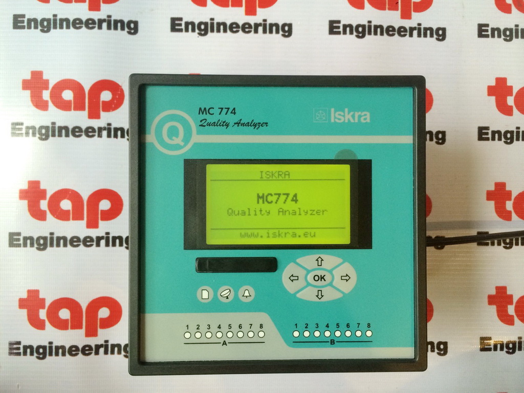
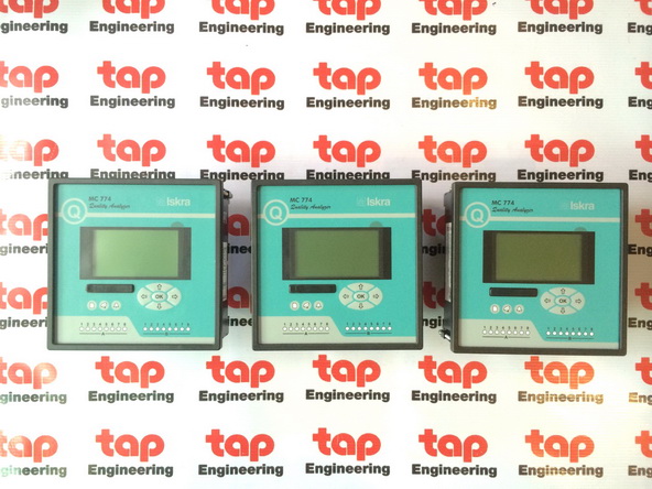
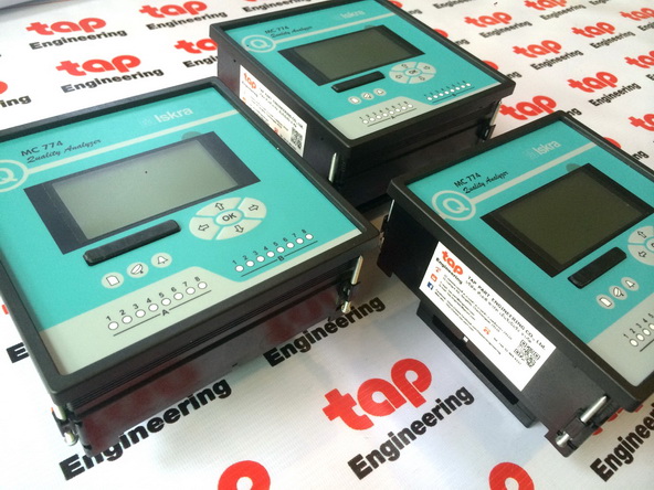
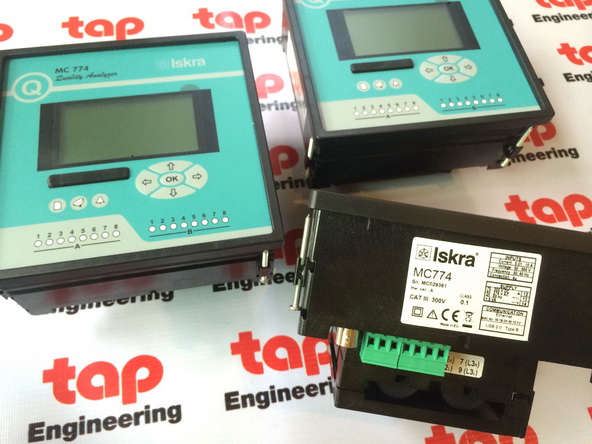
Model: MC774 POWER QUALITY METER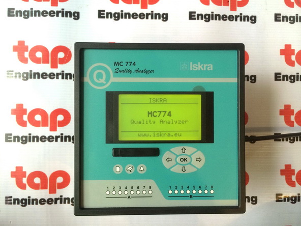
Link Download
pdf file - Datasheet MC774
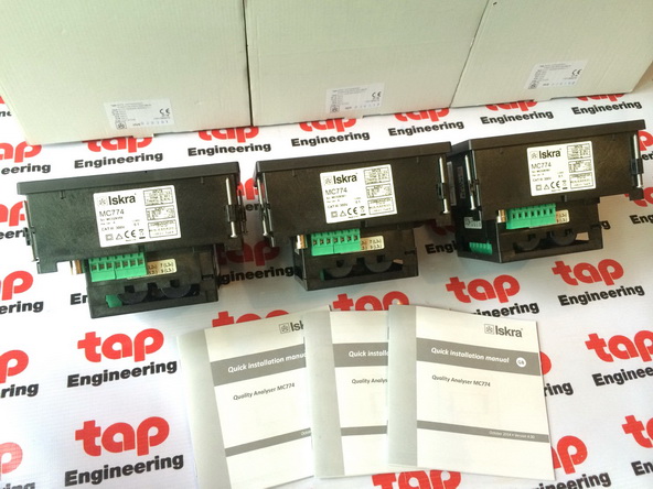
pdf file - Quick installation manual MC774
pdf file - User Manual MC774
Product of Europe
TAP Part Engineering Co., Ltd
Company in Thailand
Contact us: tap.part@engineer.com
Mobile: 091-4844332"ISKRA"
Model: MC774 POWER QUALITY METER
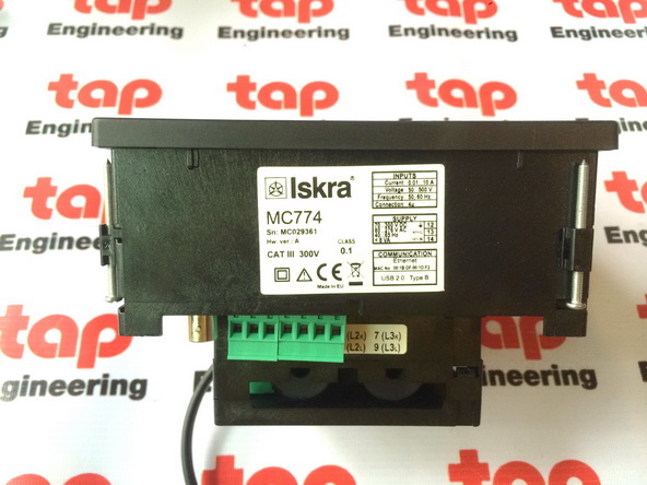
Size: 144 x 144 mm
Nominal value (In,Un) = 1 … 5A *, 50 … 500 VL-N (automatic range)
Accuracy Class 0.2S for Active Energy
Universal Auxiliary Power Supply 70-300VDC and 80-276VAC
Module: 2 Pulse output
Communication port: Ethernet RJ-45 & USB (Modbus & DNP3)
High accuracy - Class A - measurements (certified by Power Standards Lab)
EN 50160 voltage quality evaluation with automatic report generation
Web-based 3-tier centralised distributed instrument data monitoring software MiSMART
Measurements of instantaneous values of more than 140 quantities including harmonics, flicker, power line signalling voltage, unbalance...
Voltage and current auto range measurements up to 1000 V RMS, 12.5 A
4 voltage and 4 current channels with 32 micros sampling timeSerial, Ethernet and USB communication
MODBUS and DNP3 communication protocols
Support for GPS, IRIG-B and NTP real time clock synchronisation
Up to 20 I/0 modules (analogue in/out, pulse in/out, digital in/out, alarm/watchdog, tariff in)
Multilingual support
User-friendly setting and evaluation software, MiQen
Link Download
pdf file - Datasheet MC774
pdf file - Quick installation manual MC774
pdf file - User Manual MC774
Contact us: tap.part@engineer.com
Mobile: 091-4844332ISKRA Sistemi -
Quality Analyser
MC774
o Class A measuring accuracy according to EN61000-4-30
o Evaluation of power quality in compliance with EN 50160
o Voltage and current auto range measurements up to 1000VRMS, 12.5A
o 4 voltage and 4 current channels with 32μs sampling time
o Wide frequency measurement range 16 – 400 Hz
o Up to three independent communication ports (Serial, Ethernet and USB
communication)
o Support for GPS, IRIG-B and NTP real time synchronisation
o Up to 20 I/O modules (analogue in/out, pulse in/out, digital in/out,
alarm/watchdog out, tariff in)
Technical Documentation
2 MC 774 Quality Analyser
FEATURES
o Evaluation of the electricity supply quality in compliance
with EN 50160 with automatic report generation
o Measurements of instantaneous values of more than
140 quantities including harmonics, flicker, power line
signalling voltage, unbalance …
o Class A (0.1%) accuracy in compliance with EN61000-4-
30
o Four quadrant energy measurement with class 0.2S for
active energy, 8 programmable counters, up to four
tariffs, tariff clock …
o Automatic range selection of 4 current and 4 voltage
channels (max. 12.5 A and 1000 VRMS) with 32 kHz
sampling rate
o Recording all measured parameters including all voltage
and current harmonics up to 65th, 32 adjustable alarms,
anomalies and quality reports in the internal memory
o Measurements of 40 minimal and maximal values in
different time intervals (from 1 to 256 periods)
o Frequency range from 16 Hz to 400 Hz
o Up to three independent communication ports
(RS 232/485 up to 115,200 bit/s, Ethernet and USB 2.0)
o MODBUS and DNP3 communication protocols
o Support for GPS, IRIG-B (modulated and digital) and NTP
real time synchronisation
o Up to 20 inputs and outputs (analogue inputs/outputs,
digital inputs/outputs, alarm/watchdog outputs, pulse
input/outputs, tariff inputs)
o Multilingual support
o Universal power supply (two voltage ranges)
o 144 mm square panel mounting
o User-friendly setting and evaluation software, MiQen
DESCRIPTION
MC774 is an important device for permanent monitoring of
power quality from its production (especially renewable),
transmission, distribution to final consumers, who are most
affected by insufficient quality of voltage. Lack of
information about supplied quality of voltage can lead to
unexplained production problems and malfunction or even
damage to equipment used in production process.
Therefore, MC774 can be used for utility purposes
(evaluation against standards) as well as for industry
purposes (monitoring supplied power quality).
MC774 performs measurements in compliance with
regulatory requested standard EN 61000-4-30 and
evaluates recorded parameters for analysis according to
parameters defined in European supply quality standard EN
50160:2011.
Moreover MC774 stores measurements and quality reports
in internal memory for further analysis over recorded
measurements. By accessing recorded or real time values
from multiple instruments installed on different locations it
is possible to gain the overall picture of systems’ behaviour.
This can be achieved with regard to MC774 accurate
internal real time clock and wide range of synchronization
sources support, which assure accurate, time-stamped
measurements from dislocated units.
All required measurements, weekly PQ reports and alarms
can also be stored locally in an internal memory. Stored
data can be then transferred to a memory card or accessed
through communication for post analysis.
APPLICATION AND BENEFITS
MC774 Quality Analyser can be used as a standalone PQ
monitoring device for detection of local PQ deviations. For
this purpose it is normally positioned at the point-ofcommon-
coupling (PCC) of small and medium industrial and
commercial energy consumers to monitor quality of
delivered electric energy or at medium or low voltage
feeders to monitor, detect and record possible
disturbances caused by (unauthorized) operation of
consumers.
Identifying relevant fixed measuring points is the most
important task prior to complete system installation. This
system itself will not prevent disturbances in network but it
will help diagnose their origin and effects. And this is
possible only with system approach by using time
synchronized meters and predefined measuring parameters
relevant for each individual measuring point.
Therefore the most extensive benefits are achieved when
MC774 is used as a part of an energy monitoring system
comprising of strategically positioned meters connected to
MiSMART software solution. This three-tier middleware
software represents a perfect tool for utility companies,
energy suppliers and other parties on both ends of supplydemand
chain. MiSMART data collector with “push”
communication system allows automatic records of all
predefined measuring parameters. They are stored in
MiSMART database, while leaving a copy of same
parameters stored locally in memory of each device as a
backup copy. Database records in XML format can be
searched and viewed in tabelaric and graphical form using
MiSMART client or other third-party application software.
Database records can involve numerous parameters of
three-phase system, power quality parameters, physical
parameters (temp., pressure, wind speed …) as well as
alarms and detailed time-stamped event logs.
Technical Documentation
MC 774 Quality Analyser 3
COMPLIANCE WITH STANDARDS
Measurements and reports of power (voltage) quality (PQ)
indexes are only useful when can be compared with
measurements and reports from other PQ measuring devices
in the supply network and evaluated against agreed limits for
assessment of measured PQ indexes to establish an overall
view about PQ issues in the network.
For this purpose it is essential to follow guidelines described in
series of international and local standards. Beside
requirements for safe operation (LVD directive) and immunity
against more and more demanding disturbances (EMC
directive), PQ measuring depends on two levels of
standardization:
Procedures for proper acquirement of PQ indexes, their timed
aggregation and required accuracy are described in a standard
IEC EN 61000-4-30 and two supplementary standards IEC EN
61000-4-7 (harmonics), IEC EN 61000-4-15 (flickermeter)
Procedures for evaluation of measured PQ indexes according
to limit levels described in European standard EN 50160
MC774 Quality Analyser follows required procedures and
meets the precision requirements for class A measuring device
as described in standard IEC EN 61000-4-30. It uses acquired
measurements to perform automatic evaluation of PQ
according to EN 50160 and issues weekly reports. In case if
certain PQ indexes fail to meet required quality it also shows
details of problematic measurements and time of occurrence
of discrepancy.
Standard EN Description
61010-1: 2010
Safety requirements for electrical
equipment for measurement, control
and laboratory use
61557-12:2008
Electrical safety in LV distribution
systems up to 1kV a.c. and 1.5kV d.c.
– Combined performance measuring
and monitoring devices for electrical
parametrs
61000-4-30:2009
Electromagnetic compatibility (EMC)
– Power quality measurements
methods
61000-4-7:2003 +
A1:2009
Electromagnetic compatibility (EMC)
– General guide on harmonics and
interharmonics measurements
61000-4-15:2010
Electromagnetic compatibility (EMC)
– Flickermeter
50160:2011
Voltage characteristics of electricity
supplied by public distribution
networks
62053-22:2003
Electricity metering equipment -
Static meters for active energy
(classes 0,2 S and 0,5 S)
62053-23:2003
Electricity metering equipment -
Static meters for reactive energy
(classes 2 and 3)
61326-1:2006
EMC requirements for electrical
equipment for measurement, control
and laboratory use
60529:1997/A1:2000
Degrees of protection provided by
enclosures (IP code)
60068-2-1/ -2/ -6/
-27/-30
Environmental testing (-1 Cold, -2 Dry
heat, -30 Damp heat, -6 Vibration, -
27 Shock)
UL 94
Tests for flammability of plastic
materials for parts in devices and
appliances
Table 1: List of applicable standards
Technical Documentation
4 MC 774 Quality Analyser
VOLTAGE QUALITY
Voltage Quality is well defined term (sometimes also termed
Power Quality – PQ) and is covered with a selection of
parameters, each of which represents certain phenomenon.
They represent only most common types of phenomena which
can describe operation of electrical network with closest
approximation.
MC774 Quality Analyser measures, detects, stores and
evaluates parameters, which are defined in several standards.
Evaluation is by default performed according to limits set in
European standard EN50150. Beside that users can always
alter parameters according to their requirements or according
to immunity of their equipment which operates within
analyzed power network.
PQ recording settings
Figure 1 Settings for power quality parameters are set with
setting and monitoring software MiQen
Characteristic parameters that describe power quality are
shown in table 1:
Phenomena PQ Parameters
Frequency variations Frequency distortion
Voltage variations Voltage fluctuation
Voltage unbalance
Voltage changes Rapid voltage changes
Flicker
Voltage events Voltage dips
Voltage interruptions
Voltage swells
Harmonics & THD Harmonics
Interharmonics
Signalling voltage
Table 2 Voltage quality parameters as defined in EN50160
PQ reports
PQ report is issued on a basis of chosen PQ parameters as well
as information about a period of tracking and place of tracking
(type of network).
Each record is internally stored for later analysis. Settings
software allows user to quickly view PQ report with limit lines
and compliance results.
Figure 2 Viewing power quality report parameters and log
details with setting software MiQen
To analyze in details which and when certain parameters are
outside limit lines it is possible to view time stamped details
and with that establish true origin of anomaly and its
consequences.
Technical Documentation
MC 774 Quality Analyser 5
MEASUREMENTS
Online measurements
Online measurements are available on
display or can be monitored with setting and
monitoring software MiQen.
Readings on display are performed
continuously with refresh time dependent
on set average interval whereas rate of
readings monitored with MiQen is fixed and
refreshed approx. each second.
For better overview over numerous
readings, they are divided into several
groups, which contain basic measurements,
min. and max. values, harmonics, PQ
parameters and alarms.
Each group can represent data in visually
favored graphical form or detailed tabelaric
form. Latter allows freezing readings and/or
copying data into various report generation
software tools.
Interactive instrument
Additional communication feature of a
device allows interactive handling with a
dislocated device as if it would be
operational in front of user.
This feature is useful for presentations or
product training.
Selection of available quantities
Available online measuring quantities and
their appearance can vary according to set
type of power network and other settings
such as; average interval, max. demand
mode, reactive power calculation method …
Complete selection of available online
measuring quantities is shown in a table on
the next page.
Figure 3 Online measurements in graphical form – phaser diagram and
daily total active power consumption histogram
Figure 4 Online measurements in tabelaric form
Figure 5 Online harmonic measurements in graphical form
Technical Documentation
6 MC 774 Quality Analyser
Meas. type Measurement 3-phase 4-
wire
3-phase 3-
wire
1-phase comments
Phase Voltage
measurements U1-3_RMS 1ph
UAVG_RMS
Uunbalance_neg_RMS
Uunbalance_zero_RMS
U1-3_DC 1ph DC component of phase voltages
Current
I1-3_RMS 1ph
ITOT_RMS
IAVG_RMS
Power
P1-3_RMS 1ph
PTOT_RMS
Q1-3_RMS 1ph reactive power can be calculated as a squared difference
between S and P or QTOT_RMS as sample delayed
S1-3_RMS 1ph
STOT_RMS
PF1-3_RMS 1ph
ϕ1-3_RMS 1ph
Harmonic analysis
THD-U1-3 1ph
THD-I1-3 1ph
TDD-I1-3 1ph
U1-3_harmonic_1-63_% 1ph % of RMS or % of base
U1-3_harmonic_1-63_ABS 1ph
U1-3_harmonic_1-63_ϕ 1ph
U1-3_inter-harmonic_% 1ph monitoring up to 10 different fixed frequencies. % of RMS
U1-3_inter-harmonic_ABS 1ph or % of base
U1-3_signaling_% 1ph monitoring of signalling (ripple) voltage of set frequency. %
U1-3_signaling_ABS 1ph of RMS or % of base
I1-3_harmonic_1-63_% 1ph % of RMS or % of base
I1-3_harmonic_1-63_ABS 1ph
I1-3_harmonic_1-63_ϕ 1ph
Flickers
Pi1-3 1ph
Instantaneous flicker sensation measured with 150 samples
/ sec (original sampling is 1200 smpl/sec)
Pst1-3 1ph 10 min statistical evaluation (128 classes of CPF)
Plt1-3 1ph derived from 12 Pst acc. to EN 61000-4-15
Miscellaneous
K-factor1-3 1ph
Current Crest factor1-3 1ph
Phase to phase Voltage
measurements Upp1-3_RMS
UppAVG_RMS
THD-Upp1-3
Upp1-3_harmonic_1-
63_%
1ph % of RMS or % of base
Upp1-3_harmonic_1-
63_ABS
1ph
Upp1-3_harmonic_1-
63_ϕ
1ph
Uunderdeviation 1ph Uunder. and Uover. are calculated for phase or phase-to Uoverdeviation
1ph phase voltages regarding connection mode.
For more information see MC774 Quality Analyser User's manual GP K 22.444.053
Technical Documentation
MC 774 Quality Analyser 7
Table 3 cont …
Meas. type Measurement 3-phase
4-wire
3-phase
3-wire
1-phase comments
Flickers
Ppp_i1-3
Ppp_st1-3
Ppp_lt1-3
Metering Energy
Counter E1-8 each counter can be dedicated to any of four
quadrants (P-Q, import-export, L-C). Total energy is
a sum of one counter for all tariffs. Tariffs can be
fixed, date/time dependent or tariff input
dependent
E_TOT_1-8
Active tariff
Auxiliary Aux. line
channel UNEUTRAL-EARTH
aux. voltage is dedicated for neutral-earth meas.
only
measurements INEUTRAL_meas measured neutral current with 4th current input
INEUTRAL_calc calculated neutral current
INEUTRAL_err
error neutral current (difference between measured
and calculated)
Maximum Maximum demand
demand MD_I1-3 1ph
measurements MD_Pimport
MD_Pexport
MD_Qind
MD_Qcap
MD_S
Min and max Min and max
measurements U1-3_RMS_MIN 1ph
U1-3_RMS_MAX 1ph
Upp1-3_RMS_MIN
Upp1-3_RMS_MAX
I1-3_RMS_MIN 1ph
I1-3_RMS_MAX 1ph
P1-3_RMS_MIN 1ph
P1-3_RMS_MAX 1ph
PTOT_RMS_MIN 1ph
PTOT_RMS_MAX 1ph
S1-3_RMS_MIN 1ph
S1-3_RMS_MAX 1ph
STOT_RMS_MIN 1ph
STOT_RMS_MAX 1ph
freqMIN
freqMAX
Other Miscellaneous
measurements freqMEAN
Internal temp.
Date, Time
Last Sync. time UTC
GPS Time
If GPS receiver is connected to dedicated RTC time
synchronization input
GPS Longitude
GPS Latitude
GPS Altitude
For more information see MC774 Quality Analyser User's manual GP K 22.444.053
Table 3 Selection of available measurement quantities
Technical Documentation
8 MC 774 Quality Analyser
RECORDER
A built-in recorder (8Mb) enables storing measurements,
detected alarms and PQ reports with details. It supports
recording of all measured quantities including voltage and
current harmonics up tp 65th in 4 configurable partitions. For
each partition is possible to set storage interval and other
recording parameters.
Fifth partition is used for recording alarms. Each alarm
triggered by preset limit lines is stored in a form of alarm i.d.
and its timestamp.
Sixth partition is used for PQ reports. Each report in recorder
is identified by a monitoring interval (date).
Last partition is used for PQ report details. They represent
time stamped PQ values that are outside PQ limit lines.
Content of recorder can be viewed with monitoring software
MiQen in a detailed tabelaric or visually favoured graphical
form.
Memory card
MC774 Power Quality Analyzer & Recorder is equipped with
a front panel slot for full sized SD memory card that supports
capacity up to 2 GB. It is intended for downloading internally
stored data, uploading setting file and performing firmware
upgrade.
ALARMS
Alarms are powerful tool for MC774 Quality Analyser control
and supervision features. Devices’ performance can with this
features reach beyond measuring and analyzing power
network.
MC774 Quality Analyser supports recording and storing of 32
alarms in four groups. A time constant of maximal values in a
thermal mode, a delay time and switch-off hysteresis are
defined for each group of alarms.
For each parameter is possible to set limit value, condition
and alarm activation action (sound signal and/or digital
output switch if available).
All alarms are also stored in internal memory for postanalysis
Figure 6 Setting recorder parameters and viewing
memory consumption information
Figure 7 Viewing recorder content in tabelaric and
graphical form
Figure 8 Setting and viewing alarms
Technical Documentation
MC 774 Quality Analyser 9
REAL TIME SYNCHRONISATION
Synchronized real-time clock (RTC) is an essential part of any
Class A analyzer for proper chronological determination of
various events. Without RTC synchronization MC774 acts as
a Class S device.
To distinct cause from consequence, to follow a certain
event from its origin to manifestation in other parameters it
is very important that each and every event and recorded
measurement on one instrument can be compared with
events and measurements on other devices. Even if
instruments are dislocated, which is normally the case in
electro distribution network events have to be timecomparable
with accuracy better than a single period.
For this purpose instruments normally support highly
accurate internal RTC. Still this is not enough, since
temperature is location dependant and it influences its
precision. For that reason it is required to implement
periodical RTC synchronization.
MC774 Quality Analyzer supports three types of RTC
synchronization.
GPS time synchronization:
1pps and serial RS232 communication with NMEA 0183
sentence support.
GPS interface is designed as 5 pole plugable terminal (+5V for
receiver supply, 1pps input and standard RS232
communication interface).
Proposed GPS receiver is GARMIN GPS18x
IRIG time code B (IRIG-B):
Unmodulated (DC 5V level shift) and modulated (1 kHz) serial
coded format with support for 1pps, day of year, current
year and straight seconds of day as described in standard
IRIG-200-04. Supported serial time code formats are IRIGB007
and IRIG-B127.
Interface for modulated IRIG-B is designed as BNC-F terminal
with 600 input impedance. Interface for unmodulated IRIGB
is designed as pluggable terminal.
Network time protocol (NTP):
Synchronization via Ethernet requires access to a NTP
server.
Note: NTP can usually maintain time to within tens of
milliseconds over the public Internet, but the accuracy
depends on infrastructure properties - asymmetry in
outgoing and incoming communication delay affects
systematic bias. It is recommended that dedicated
network rather than public network is used for
synchronisation purposes.
COMMUNICATION
MC774 Quality Analyzer has a wide variety of
communication possibilities to suit specific demands. It is
equipped with standard communication port COM1 and
auxiliary communication port COM2. This allows two
different users to access data from a device simultaneously
and by using TCP/IP communication, data can be accessed
worldwide.
COM2 port is always present as a part of synchronization
module C. It is available as a general purpose communication
port when it is not used for time synchronization purposes.
Different configurations are possible (to be specified with an
order).
Configuration COM1 COM2(2)
1 RS232/485 /
2 RS232/485 RS232/485
3 USB /
4 USB RS232/485
5(1) Ethernet & USB /
6(1) Ethernet & USB RS232/485
(1) Galvanic separation between Eth. and USB is 1 kVACRMS
(2) COM2 is NOT available if GPS time synchronization is used
Table 3: List of communication configurations
MC774 Quality Analyser supports standard communication
protocols MODBUS RTU, TCP and DNP3 L1.
Additionally it supports proprietary PUSH communication
mode, which is used in system applications where devices
send predefined readings in predefined time intervals in XML
format. Web based software MiSMART collects data and
stores it into database. Stored data can then be viewed with
MiSMART client software.
For more information about PUSH communication mode and
XML format see MC774 Quality Analyser User's manual
GP K 22.444.053
Figure 9 MiSMART client window
Technical Documentation
10 MC 774 Quality Analyser
TECHNICAL DATA
Measurement inputs
Nominal frequency range 50, 60 Hz
Measuring frequency range 16−400 Hz
Voltage measurements:
Number of channels 4 (1)
Sampling rate 31 kHz
Min. voltage for sync. 1 Vrms
Nominal value (UN) 500 VLN , 866 VLL
Max. measured value (cont.) 600 VLN ; 1000 VLL
Max. allowed value 1.2 × UN permanently
2 × UN ; 10 s
Consumption < U2 / 4.2MΩ per phase
Input impedance 4.2MΩ per phase
(1) 4th channel is used for measuring U EARTH-NEUTRAL
Current measurements:
Number of channels 4
Sampling rate 31 kHz
Nominal value (INOM) 1 A, 5 A
Max. measured value (I1-I3 only) 12.5 A sin.
Max. allowed value (thermal) 15 A cont.
≤ 300 A; 1s
Consumption < I2 × 0.01Ω per phase
System:
Voltage inputs can be connected either directly to lowvoltage
network or via a VT to higher voltage network.
Current inputs can be connected either directly to lowvoltage
network or shall be connected to network via a
corresponding CT (with standard 1 A or 5 A outputs).
For more information about different system connections
see CONNECTION on page 13.
Basic accuracy under reference conditions
Accuracy is presented as percentage of reading of the
measurand except when it is stated as an absolute value.
Measurand Accuracy
Voltage L-N, L-L ± 0.1% acc. to EN 61557-12
Current ± 0.1% acc. to EN 61557-12
Active power (IN = 5A) ± 0.2% acc. to EN 61557-12
Active power (IN = 1A) ± 0.5% acc. to EN 61557-12
Active energy Cl. 0.2S acc. to EN 62053-22
Reactive energy Cl.2 acc. to EN 62053-23
Frequency (f) ± 0.01Hz acc. to EN 61557-12
Power factor (PF) ± 0.5% acc. to EN 61557-12
THD (U) ± 0.3% acc. to EN 61557-12
THD (I) ± 0.3% acc. to EN 61557-12
Real time clock (RTC) < ± 1s / day acc. to IEC61000-4-30
All values required for PQ analysis, which should be
measured according to IEC61000-4-30 correspond to
Class A accuracy.
For complete overview of accuracy for all measured
parameters and measuring ranges see Users’ manual (doc.
no. GB K 22.444.053) on page 143.
INPUT / OUTPUT modules
MC774 Quality Analyser is equipped with two main I/O slots,
two auxiliary I/O slots and special time-synchronisation
module. The following I/O modules are available:
Module type Number of modules per slot
Main slot Aux slot
Analogue output (AO) 2 /
Analogue input (AI) 2 /
Digital output (DO) 2 8
Digital input (DI) 2 8
Bistable Digital output (BO) 1 /
Status output (WO) 1 + 1xDO /
Table 4: List of available I/O modules
Analogue input (AI):
Three types of analogue inputs are suitable for acquisition of
low voltage DC signals from different sensors. According to
application requirements it is possible to choose current,
voltage or resistance (temperature) analogue input. They all
use the same output terminals.
MiQen software allows setting an appropriate calculation
factor, exponent and required unit for representation of
primary measured value (temperature, pressure, wind speed
…)
DC current input:
Nominal input range –20…0…20 mA (±20%)
input resistance 20 Ω
accuracy 0.5 % of range
temperature drift 0.01% / °C
conversion resolution 16 bit (sigma-delta)
Analogue input mode internally referenced Single-ended
DC voltage input:
Nominal input range –10…0…10 V (±20%)
input resistance 100 kΩ
accuracy 0.5 % of range
temperature drift 0.01% / °C
conversion resolution 16 bit (sigma-delta)
Analogue input mode internally referenced Single-ended
Resistance (temperature) input:
Nominal input range (low)* 0 - 200 Ω (max. 400 Ω)
PT100 (-200°C–850°C)
Nominal input range (high)* 0 – 2 kΩ (max. 4 kΩ)
PT1000 (-200°C–850°C)
connection 2-wire
accuracy 0.5 % of range
conversion resolution 16 bit (sigma-delta)
Analogue input mode internally referenced Singleended
* Low or high input range and primary input value
(resistance or temperature) are set by the MiQen
setting software
Technical Documentation
MC 774 Quality Analyser 11
Analogue output (AO):
Output range 0…20 mA
Accuracy 0.5% of range
Max. burden 150 Ω
Linearization Linear, Quadratic
No. of break points 5
Output value limits ± 120% of nominal output
Response time
(measurement and
analogue output)
depends on set general average
interval
(0.1s – 5s)
Residual ripple < 1 % p.p.
Outputs may be either short or open-circuited. They are
electrically insulated from each other and from all other
circuits.
Output range values can be altered subsequently (zoom scale)
using the setting software, but a supplementary error results.
Digital input (DI)
Purpose Tariff input, Pulse input, General
purpose digital input
Max. current 8 mA (48V), <0.6mA (110, 230V)
SET voltage 40...120 % of rated voltage
RESET voltage 0...10 % of rated voltage
Tariff input Main slot only
Rated voltage (5…48), 110, 230 ± 20% VAC/DC
Frequency range 45…65 Hz
Pulse input Main slot only
Rated voltage 5 - 48VDC
Min. pulse width 0.5 ms
Min. pulse period 2 ms
Digital input (5…48), 110, 230 ± 20% VAC/DC
Min. signal width 20 ms
Min. pause width 40 ms
Digital output (DO, BO)
Type Relay switch
Purpose Alarm output, General purpose digital
output
Rated voltage 230 VAC/DC ± 20% max
Max. switching current 1000 mA (main slot)
100 mA (aux. slot, DO only)
Contact resistance ≤ 100 mΩ (100 mA, 24V)
Impulse Max. 4000 imp/hour
Min. length 100 ms
Type Optocoupler open collector switch
(main slot only)
Purpose Pulse output
Rated voltage 40 VAC/DC
Max. switching current 30 mA (RONmax = 8Ω)
Pulse length programmable (2 … 999 ms)
Status (watchdog) output (WO)
Time synchronisation input
Digital input GPS or IRIG-B TTL
1pps voltage level TTL level (+5V)
Time code telegram RS232 (GPS)
DC level shif (IRIG-B)
AM analogue input RIG-B AM modulated
Carrier frequency 1 kHz
Input impedance 600 Ohms
Amplitude 2.5VP-Pmin, 8VP-Pmax
Modulation ration 3:1 – 6:1
Universal Power Supply
Standard (high): CAT III 300V
Nominal voltage AC 80 … 276 V
Nominal frequency 40 … 65 Hz
Nominal voltage DC 70 … 300 V
Consumption (max. all I/O) < 8VA
Power-on transient current < 20 A ; 1 ms
Optional (low): CAT III 300V
Nominal voltage AC 48 … 77 V
Nominal frequency 40 … 65 Hz
Nominal voltage DC 19 … 70 V
Consumption (max. all I/O) < 8VA
Power-on transient current < 20 A ; 1 ms
Safety:
Protection: protection class II
functional earth terminal must be
connected to earth potential!
Voltage inputs via high impedance
Double insulation for I/O ports and
COM ports
Pollution degree 2
Installation category CAT II ; 600 V
(measuring inputs) CAT III ; 300 V
Acc. to EN 61010-1
Test voltages UAUX↔I/O, COM1: 3510 VACrms
UAUX↔U, I inputs: 3510 VACrms
U, I inputs↔I/O, COM1: 3510 VACrms
HV I/O ↔ I/O, COM1: 3510 VACrms
U inputs↔I inputs: 3510 VACrms
Technical Documentation
12 MC 774 Quality Analyser
Mechanical
Dimensions 144 × 144 ×100 mm
Mounting Panel mounting 144×144 mm
Required mounting hole 137 × 137 mm
Enclosure material PC/ABS
Flammability Acc. to UL 94 V-0
Weight 550 g
Enclosure material PC/ABS
Acc. to UL 94 V-0
Ambient conditions:
Ambient temperature K55 temperature class
Acc. to EN61557-12
-10…55 °C
Storage temperature -40 to +70 °C
Average annual humidity ≤ 90% r.h. (no condensation)
Pollution degree 2
Enclosure protection IP 40 (front plate)
IP 20 (rear side)
Installation altitude ≤ 2000 m
Real time clock
A built-in real time clock is also without external
synchronization very stable when device is connected to
auxiliary power supply. For handling shorter power
interruptions without influence on RTC, device uses high
capacity capacitor. It ensures auxiliary supply (for internal RTC
only) for more than two days of operation.
Type Low power embedded RTC
RTC stability < 1 sec / day
Connection cables
MC774 Quality Analyser is equipped with European style
pluggable terminals for measuring voltages, auxiliary supply,
communication and I/O modules. Measuring current cables
shall be attached as through-hole connection without
screwing.
NOTE!
Stranded wire must be used with insulated end sleeve to
assure firm connection.
Voltage inputs (4) ≤ 2.5 mm2 , AWG 24-12 single wire
Current inputs (3) ≤ Ø 6 mm one conductor with insulation
Supply (3) ≤ 2.5 mm2 , AWG 24-12 single wire
Com (5), I/O (6) ≤ 2.5 mm2 , AWG 24-12 single wire
MiQen - setting and acquisition Software
MiQen software is intended for supervision of MC774 and
many other instruments on a PC. Network and the device
setting, display of measured and stored values and analysis of
stored data in the device are possible via the serial, Ethernet or
USB communication. The information and stored
measurements can be exported in standard Windows formats.
Multilingual software functions on Windows XP, W7 operating
systems.
Figure 9 MiQen setting and acquisition software
MiQen software is intended for:
Setting all of the instruments parameters (online and offline)
Viewing current measured readings and stored data
Setting and resetting energy counters
Complete I/O modules configuration
Evaluation of the electricity supply quality in compliance with
SIST EN 50160
Viewing and exporting time-stamped PQ anomaly details
Upgrading instruments firmware
Searching the net for devices
Virtual interactive instrument
Comprehensive help support
Technical Documentation
MC 774 Quality Analyser 13
CONNECTION
System/ connection Terminal assignment
1b (1W1b)
Single-phase connection
3b (1W3b)
Three-phase, three-wire connection with balanced
load
3u (2W3u)
Three-phase, three-wire connection with
unbalanced load.
Technical Documentation
14 MC 774 Quality Analyser
System/ connection Terminal assignment
4b (1W4b)
Three-phase, four wire connection with balanced
load
4u (3W4)
Three-phase, four wire connection with
unbalanced load. With this connection, a neutral
current can be measured with 4th current sensor.
NOTE:
With all connection schemes must be terminal 12 (PE) ALWAYS connected.
Fourth voltage channel is dedicated for measuring voltage between EARTH (PE, terminal 12) and NEUTRAL (N, terminal 2).
Technical Documentation
MC 774 Quality Analyser 15
DIMENSIONAL DRAWING
Connection table
Function Connection Comment
Measuring input:
AC current
IL1 1/3
CAT II 600V
CAT III 300V
IL2 4/6
IL3 7/9
ILN 26/27
AC voltage
UL1 2
CAT II 600V
CAT III 300V
UL2 5
UL3 8
UN 11
Inputs / outputs:
Module 1/2
+ 15
(common) 16
+ 17
Module 3/4
+ 18
(common) 19
+ 20
Module A 30-38
Module B 40-48
Module C 52-58
Auxiliary power supply:
+ / AC (L) 13
CAT III 300V
GROUND terminal must be always
connected ‼
– / AC (N) 14
GROUND 12
Communication:
RS485
A 21
RS232 and RS485 are both supported, but only
one at the time can be used!
In case of Ethernet / USB communication,
terminals from 21 to 25 are not used
(unconnected).
B 22
RS232
RX 23
GND 24
TX 25
Table 4: Connections
Technical Documentation
16 MC 774 Quality Analyser
DATA FOR ORDERING
When ordering MC774 Quality Analyser, all required specifications shall be stated in compliance with the ordering code. Additional
information could be stated. Note that fixed or programmable specifications are not part of ordering code
General ordering code
The following specifications shall be stated:
Nominal freq.
Aux. supply
Comm. type
I/O1 module
I/O2 module
I/OA module
I/OB module
MC774 x x x x x x x
| | | | | | |
| | | | | M 8× Relay output
| | | | | D 8x Digital input (230VAC/DC)
| | | | | E 8x Digital input (110VAC/DC)
| | | | | F 8x Digital input (48VAC/DC)
| | | | | N Without
| | | | |
| | | A 2× Analogue output
| | | S 2× Pulse output
| | | M 2× Relay (alarm) output
| | | B 1× Bistable Relay (alarm) output
| | | I 2× Analogue input (mADC)
| | | U 2× Analogue input (VDC)
| | | R 2× Analogue input (R/Temp.)
| | | D 2× Digital input (230 VAC/DC)
| | | E 2× Digital input (110 VAC/DC)
| | | F 2× Digital input (5…48 VAC/DC)
| | | P 2× Pulse input (5 – 48 VDC)
| | | T 2× Tariff input (230 VAC/DC) I/O1 only
| | | Z 2× Tariff input (110 VAC/DC) I/O1 only
| | | Y 2× Tariff input (5…48 VAC/DC) I/O1 only
| | | W 1× Status output + 1× Relay (alarm) output
| | | N Without
| | |
| | T RS232/485 Plugable terminals
| | E Ethernet & USB
| | U USB
| |
| H Universal HIGH (70...300 VDC, 80...276 VAC)
| L Universal LOW (19...70 VDC, 48...77 VAC)
|
S 50, 60 Hz
A 400 Hz
Technical Documentation
MC 774 Quality Analyser 17
Example of ordering:
MC774 with a universal-HI supply is connected to a secondary phase voltage up to 500 VL-N and 5 A secondary current on 50Hz
network. Ethernet & USB communication, watchdog output (plus one relay output) as I/O1, 2x digital input 230V as I/O2, 8x digital
input as I/OA and 8x relay output as I/OB.
Voltage and current nominal value are due to auto-range fixed to max. nominal value and are therefore omitted from ordering
code.
Connection type is user programmable and is therefore omitted from ordering code. Default is 4u connection.
Example ordering code:
MC774 S H E W D D M
| | | | | | |
| | | | | | 8× Relay output
| | | | | 8x Digital input (230 VAC/DC)
| | | | 2× Digital input (230 VAC/DC)
| | | 1× Watchdog output + 1× Relay (alarm) output
| | Ethernet & USB
| Universal HIGH (70...300 VDC, 80...276 VAC)
50, 60 Hz
Dictionary:
PQ Power Quality alias Voltage Quality
RMS Root Mean Square
PA Power angle (between current and voltage)
PF Power factor
VT Voltage measuring transformer
CT Current measuring transformer
THD Total harmonic distortion
Ethernet IEEE 802.3 data layer protocol
MODBUS / DNP3 Industrial protocol for data transmission
MiQen ISKRA setting and acquisition Software
AC Alternating quantity
RTC Real Time Clock
IRIG Inter-range instrumentation group time codes
NTP Network Time Protocol
Technical Documentation
18 MC 774 Quality Analyser


ระบบสมาชิก
DHL Express

FedEx Express

TNT Express

UPS Tracking

USPS Tracking

KERRY Express

EMS & Thailandpost Tracking


▲
▼
รายการสั่งซื้อของฉัน
รายการสั่งซื้อของฉัน
ข้อมูลร้านค้านี้

บริษัท ทีเอพี พาร์ท เอ็นจิเนียริ่ง จำกัด
บ.ทีเอพี พาร์ทฯ ก่อตั้งขึ้นเมื่อปี 2551 โดยกลุ่มวิศกรที่มีประสบการณ์ เราจำหน่าย-เป็นผู้นำเข้าสินค้าเองโดยตรงจากต่างประเทศ อาทิ เครื่องจักร อะไหล่วิศวกรรม อุปกรณ์ไฟฟ้าคอนโทรล เครื่องมือวัด และอุปกรณ์ต่างๆที่ใช้ในทุกกลุ่มอุตสาหกรรม ต่อมาด้วยประสบการณ์ต่างๆ เราสามารถขยายธุรกิจโดยการเป็นตัวแทนจำหน่าย รวมถึงบริการติดตั้งโครงการระบบควบคุมและสั่งการอุปกรณ์ไฟฟ้า
เบอร์โทร : 091-484-4332
อีเมล : info@tap-part.com
อีเมล : info@tap-part.com
ส่งข้อความติดต่อร้าน
เกี่ยวกับร้านค้านี้
ค้นหาสินค้าในร้านนี้
ค้นหาสินค้า
สินค้าที่ดูล่าสุด
บันทึกเป็นร้านโปรด
Join เป็นสมาชิกร้าน
แชร์หน้านี้
แชร์หน้านี้
↑
TOP เลื่อนขึ้นบนสุด
TOP เลื่อนขึ้นบนสุด
สินค้าในตะกร้า ({{total_num}} รายการ)

ขออภัย ขณะนี้ยังไม่มีสินค้าในตะกร้า
ราคาสินค้าทั้งหมด
฿ {{price_format(total_price)}}
- ฿ {{price_format(discount.price)}}
ราคาสินค้าทั้งหมด
{{total_quantity}} ชิ้น
฿ {{price_format(after_product_price)}}
ราคาไม่รวมค่าจัดส่ง
รวมภาษีมูลค่าเพิ่มแล้ว
➜ เลือกซื้อสินค้าเพิ่ม