ISKRA MC750ATH
1 ปีที่ผ่านมา
ISKRA MC750ATH
Made in Europe
TAP Part Engineering Co., Ltd.Made in Europe
Company in Thailand
Contact us: tap.part@engineer.com
Mobile: 091-4844332
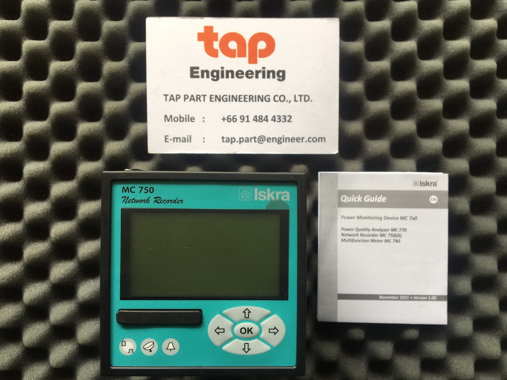
ISKRA MC750ATH Network Recoreder Meter
Ordering Code MC750ATH-SUENCCB
Communication Port Ethernet RJ-45 & USB (Mosbus+DNP3)
Made in Europe


ต้องการสอบถามราคา รายละเอียดสินค้า กรุณาแจ้งยี่ห้อ รุ่น จำนวน เข้ามาที่
Mobile: 091-484-4332
Email: tap.part@engineer.com


NETWORK RECORDER MC750ATH
o Measurements of instantaneous values of more than 140 quantities.
o Class S measuring accuracy according to EN61000-4-30.
o Voltage and current auto range measurements up to 1000 VRMS, 12.5 A.
o Wide frequency measurement range 16 Hz – 400 Hz.
o Up to three independent communication ports.
o Support for NTP real time synchronisation.
o Up to 4 inputs/ouputs.
Technical Documentation
2 MC750ATH Network Recorder
NOTE!
This data sheet is valid for the MC750ATH Network recorder with hardware version D.
FEATURES
o Measurements of instantaneous values of more than 140 quantities (U, I, P, Q, S, PF, PA, f, φ, THD, MD, energy, energy cost by tariffs, etc.).
o Measuring methods accuracy is class S (0.2%) according to EN61000-4-30.
o Four quadrant energy measurement with class 0.5 S for active and 1 for reactive energy (8 programmable energy counters, up to four tariffs, tariff clock, etc.).
o Automatic range selection of 3 current and 4 voltage channels (max. 12.5 A and 1000 VRMS) with 32 kHz sampling rate.
o Recording all measured parameters including all voltage and current harmonics up to 63rd, 32 adjustable alarms in the internal memory (8 MB flash).
o Measurements of 40 minimal and maximal values in different time intervals (from 1 period to 256 periods).
o Frequency range from 16 Hz to 400 Hz.
o Up to three independent communication ports (RS232 or RS485 up to 115,200 bit/s, Ethernet and USB 2.0).
o MODBUS and DNP3 communication protocols.
o Support for NTP real time synchronisation.
o Memory card (MMC or SD) for data transmission, setting and upgrading.
o Universal or AC power supply.
o Graphical LCD; (128 x 64) dots with illumination.
o Up to 4 inputs or outputs (analogue, pulse, relay and watchdog outputs, digital, tariff, pulse and analogue inputs).
o Multilingual support.
o 96 mm square panel mounting.
o User-friendly PC MiQen software.
o Extension unit with four configurable analogue outputs – EX104 (0.4 mADC … 20 mADC, 0 VDC … 10 VDC).
DESCRIPTION
MC750ATH is an important device for permanent monitoring measuring and analysing single-phase or three-phase electrical power network.
The meter measures RMS value according to the principle of fast sampling of voltage and current signals. A built-in microprocessor calculates measurands (voltage, current, frequency, energy, power, power factor, THD phase angles, etc.) from the measured signals.
MC750ATH performs measurements in compliance with regulatory requested standard EN 61000-4-30.
All required measurements and alarms can also be stored locally in an internal memory. With the RS232/RS485 or Ethernet/USB communication the meter can be set, measurements checked and stored data downloaded.
APPLICATION AND BENEFITS
MC750ATH Network recorder is intended for monitoring, measuring and recording of electrical quantities of a three-phase electric-energy distribution system.
Identifying relevant fixed measuring points is the most important task prior to complete system installation. This system itself will not prevent disturbances in network but it will help diagnose their origin and effects. This is possible only with system approach by using time synchronized meters with wide range of measuring parameters.
Technical Documentation
MC750ATH Network Recorder 3
Database records can involve numerous parameters of three-phase system, power quality parameters, physical parameters (temp., pressure, wind speed …) as well as alarms and detailed time-stamped event logs.
NOTE!
Stored data depends on device type and settings.
COMPLIANCE WITH STANDARDS
MC750ATH Network recorder follows required procedures and meets the precision requirements for class S measuring device as described in standard IEC EN 61000-4-30. Standard EN Description
61010-1: 2010
Safety requirements for electrical equipment for measurement, control and laboratory use.
61557-12:2008
Electrical safety in LV distribution systems up to 1 kV a.c. and 1.5 kV d.c. – Combined performance measuring and monitoring devices for electrical parameters.
62053-21*
Electricity metering equipment (a.c.) Particular requirements.
62053-22:2003*
Electricity metering equipment - Static meters for active energy (classes 0.2 S and 0.5 S).
62053-23:2003*
Electricity metering equipment -Static meters for reactive energy (classes 2 and 3).
61326-1:2006
EMC requirements for electrical equipment for measurement, control and laboratory use.
60529:1997/A1:2000
Degrees of protection provided by enclosures (IP code).
62052−11*
Electricity metering equipment – General requirements, tests and test conditions.
62053-31
Electricity metering equipment (a.c.) Particular requirements.
Table 1: List of applicable standards
* − Partial compliance
DESCRIPTION OF PROPERTIES
Measurands
RMS values of currents and voltages.
Measurements of energy, power and power factors in all 4 quadrants.
Minimal/maximal values.
Average values of measurands per interval.
Measurement of THD values of current and voltage (from 0 to 400 %).
Harmonic analysis of phase, phase-to-phase voltages and currents up to the 63rd harmonic.
Recorder
A built-in recorder (8 Mb) enables storing of up to 128 measurements and detected alarms (up to 32).
Memory card
The meter is provided with a slot for a full size SD* (128 MB to 2 GB) memory card formatted to FAT16 that can be used for transfer of measurements from the internal memory, meter setting and software updating.
* - Please note that not all SD memory cards are supported. Order at Iskra, d.o.o. to assure functionality.
Alarms
Alarms are powerful tool for MC750ATH Network recorder control and supervision features.
MC750ATH Network recorder supports recording and storing of 32 alarms in four groups. A time constant of maximal values in a thermal mode, a delay time and switch-off hysteresis are defined for each group of alarms.
For each parameter is possible to set limit value, condition and alarm activation action (sound signal and/or digital output switch if available).
Technical Documentation
4 MC750ATH Network Recorder
Real time synchronisation
Network time protocol (NTP):
MC750ATH Network recorder supports NTP time synchronisation. Ethernet access to NTP server is required for proper operation.
NOTE!
NTP can usually maintain time to within tens of milliseconds over the public Internet, but the accuracy depends on infrastructure properties - asymmetry in outgoing and incoming communication delay affects systematic bias. It is recommended that dedicated network rather than public network is used for synchronisation purposes.
Communication
MC750ATH Network recorder has a wide variety of communication possibilities to suit specific demands. The meter is equipped with RS232/RS485 (DB9 or terminal connection) or Ethernet (RJ-45 terminal) and USB (USB-B type) communication. It can also be equipped with communication port for EX104 extension unit.
COM2 port is optional and can be ordered as one of I/O modules.
Different configurations are possible (to be specified with an order). Configuration COM1 COM2
1
RS232/485
/ 2 RS232/485 RS232 or 485
3(1)
Ethernet & USB
/ 4(1) Ethernet & USB RS232 or RS485
(1) Galvanic separation between Eth. and USB is 1 kVACRMS
Table 2: List of communication configurations
MC750ATH Network recorder supports standard communication protocols MODBUS RTU, MODBUS TCP and DNP3.
Analogue extender EX104 (accessory)
If there is a demand for additional analogue outputs analogue extender EX104 can be used.
It is a standalone unit, connected to meter via module 2 (module for communication with EX104 needs to be specified at order). Up to 4 analogue outputs can be used with one meter. More information can be found in Analogue extender EX104 data sheet (E P22.495.400).
Supply
Power supply connection of the meters is adaptive. A universal power supply enables connection of the meter to DC (20 V−300 V) or AC voltage (48 V − 276 V, 40 Hz ... 70 Hz).
AC power supply enables connection of the meter to AC voltage.
Handling the costs
A special meter function is cost evaluation of energy (active, reactive and total) per tariffs. The meter itself enables tracing the costs in optional currency and calculates consumption by means of the adjustable tariff clock and electric energy price.
Technical Documentation
MC750ATH Network Recorder 5
Miqen
MiQen software is intended for supervision of the meter on PC. Network and the meter setting, display of measured, stored values and analysis of data from the meter are possible via serial, Ethernet or USB communication. The information and stored measurements can be exported in standard Windows formats. Multilingual software functions on Windows XP operating system or higher. MiQen can be downloaded from Iskra, d.o.o. webpage www.iskra.eu.
Figure 1 Sample of MiQen setting and acquisition software
MiQen software is intended for:
Setting all of the instruments parameters (online and offline).
Viewing current measured readings and stored data.
Setting and resetting energy counters.
Complete I/O modules configuration.
Evaluation of the electricity supply quality in compliance with SIST EN 50160.
Viewing and exporting time-stamped PQ anomaly details.
Upgrading instruments firmware.
Searching the net for devices.
Virtual interactive instrument.
Comprehensive help support.
NOTE!
MiQen software functions depend on the type of connected device.
Data display
Data are displayed on (128 x 64) dot graphic LCD with illumination 37 mm x 69 mm. Indication symbols on the front side are optical LEDs indicating energy flow, access to memory card and active alarm.
Technical Documentation
6 MC750ATH Network Recorder
MEASUREMENTS
Online measurements
NOTE!
In MiQen settings, software device will represent itself as MC 750A.
Online measurements are available on display or can be monitored with setting and monitoring software MiQen.
Readings on display are performed continuously with refresh time dependent on set average interval whereas rate of readings monitored with MiQen is fixed and refreshed approx. each second.
For better overview over numerous readings, they are divided into several groups, which contain basic measurements, min. and max. values, harmonics and alarms.
Each group can represent data in visually favored graphical form or detailed tabelaric form. Latter allows freezing readings and/or copying data into various report generation software tools.
Interactive instrument
Additional communication feature of a device allows interactive handling with a dislocated device as if it would be operational in front of user.
This feature is useful for presentations or product training.
Selection of available quantities
Available online measuring quantities and their appearance can vary according to set type of power network and other settings such as; average interval, max. demand mode, reactive power calculation method.
Complete selection of available online measuring quantities is shown in a table on the next page.
Figure 2 Sample of online measurements in graphical form – phase diagram and daily total active power consumption histogram
Figure 3 Sample of online measurements in tabular form
Figure 4 Sample of online harmonic measurements in graphical form
Technical Documentation
MC750ATH Network Recorder 7
Meas. type
Measurement
3-phase 4-wire
3-phase 3-wire
1-phase
comments
Phase
Voltage
measurements
U1-3_RMS
1ph
UAVG_RMS
U1-3_DC
1ph
DC component of phase voltages
Current
I1-3_RMS
1ph
ITOT_RMS
IAVG_RMS
INEUTRAL_calc
calculated neutral current
Power
P1-3_RMS
1ph
PTOT_RMS
Q1-3_RMS
1ph
reactive power can be calculated as a squared difference between S and P or as delayed sample
QTOT_RMS
Qb1-3_RMS
1ph
Budeanu reactive power Phase
QbTOT_RMS
Budeanu reactive power Total
S1-3_RMS
1ph
STOT_RMS
PF1-3_RMS
1ph
PFTOT_RMS
1-3_RMS
1ph
PA – Power angle
Harmonic analysis
THD-U1-3
1ph
THD-I1-3
1ph
TDD-I1-3
1ph
U1-3_harmonic_1-63_%
1ph
% of RMS or % of base
U1-3_harmonic_1-63_ABS
1ph
U1-3_harmonic_1-63_
1ph
I1-3_harmonic_1-63_%
1ph
% of RMS or % of base
I1-3_harmonic_1-63_ABS
1ph
I1-3_harmonic_1-63_
1ph
Phase to phase
Voltage
measurements
Upp1-3_RMS
UppAVG_RMS
THD-Upp1-3
x-y_RMS
Phase-to-phase angle
Upp1-3_harmonic_1-63_%
1ph
% of RMS or % of base
Upp1-3_harmonic_1-63_ABS
1ph
Upp1-3_harmonic_1-63_
1ph
For more information see MC750ATH Network recorder User's manual.
Table 3: Selection of available measurement quantities
Technical Documentation
8 MC750ATH Network Recorder
Meas. type
Measurement
3-phase 4-wire
3-phase 3-wire
1-phase
comments
Metering
Energy
Counter E1-8
each counter can be dedicated to any of four quadrants (P-Q, import-export, L-C). Total energy is a sum of one counter for all tariffs. Tariffs can be fixed, date/time dependent or tariff input dependent
E_TOT_1-8
Active tariff
Maximum
Maximum demand
demand
MD_I1-3
1ph
measurements
MD_Pimport
MD_Pexport
MD_Qind
MD_Qcap
MD_S
Min and max
Min and max
measurements
U1-3_RMS_MIN
1ph
U1-3_RMS_MAX
1ph
Upp1-3_RMS_MIN
Upp1-3_RMS_MAX
I1-3_RMS_MIN
1ph
I1-3_RMS_MAX
1ph
P1-3_RMS_MIN
1ph
P1-3_RMS_MAX
1ph
PTOT_RMS_MIN
1ph
PTOT_RMS_MAX
1ph
S1-3_RMS_MIN
1ph
S1-3_RMS_MAX
1ph
STOT_RMS_MIN
1ph
STOT_RMS_MAX
1ph
freqMIN
freqMAX
Other
Miscellaneous
measurements
freqMEAN
Internal temp.
Date, Time
Last Sync. time
UTC
For more information see MC750ATH Network recorder User's manual.
Table 3: Selection of available measurement quantities
Technical Documentation
MC750ATH Network Recorder 9
TECHNICAL DATA
Measurement inputs
Nominal frequency range
50 Hz, 60 Hz
Measuring frequency range
16 Hz−400 Hz
Voltage measurements:
Number of channels
4 (1)
Sampling rate
32 kHz
Min. voltage for sync.
1 Vrms
Nominal value (UN)
500 VLN , 866 VLL
Max. measured value (cont.)
600 VLN ; 1000 VLL
Max. allowed value
1.2 × UN permanently
2 × UN ; 10 s
Consumption
< U2 / 4.2 MΩ per phase
Input impedance
4.2 MΩ per phase
(1) 4th channel is used for measuring U EARTH-NEUTRAL
Current measurements:
Number of channels
3
Sampling rate
32 kHz
Nominal value (INOM)
1 A, 5 A
Max. measured value (I1-I3 only)
12.5 A sin
Max. allowed value (thermal)
15 A cont.
≤ 300 A; 1 s
Consumption
< I2 × 0.01 Ω per phase
Basic accuracy under reference conditions
Accuracy is presented as percentage of reading of the measurand except when it is stated as an absolute value. Measurand Accuracy According to
Voltage L-N, L-L
± 0.2%
EN 61557-12
Current
± 0.2%
EN 61557-12
Active power (IN = 5 A)
± 0.5%
EN 61557-12
Active power (IN = 1 A)
± 0.5%
EN 61557-12
Active energy
Cl. 0.5S
EN 62053-22
Reactive energy
Cl.1
EN 62053-24
Frequency (f)
± 0.02%
EN 61557-12
Power factor (PF)
± 0.5%
EN 61557-12
THD (U)
± 0.3%
EN 61557-12
THD (I)
± 0.3%
EN 61557-12
Real time clock (RTC)
< ± 1s/day
IEC61000-4-30
Table 4: Accuracy of measurands.
For complete overview of accuracy for all measured parameters and measuring ranges see Users’ manual.
INPUT/OUTPUT modules
The modules are available with double inputs/outputs. Each module has three terminals.
The meter is available without, with one or with two modules. Module type Number of I/O per module
Relay output (RO)
2 Analogue output (AO) 2 x 20 mA Analogue input (AI) 2 Pulse output (PO) 2 Pulse input (PI) 2 Bistable Digital output (BO) 1
Digital output (DO)
2 Digital input (DI) 2 Tariff input (TI) 2 Additional communication port (COM2) 1
Status output (WO)
1 + 1xRO Communication port for analogue extender EX104 1
Table 5: List of available I/O modules
Analogue input (AI):
Three types of analogue inputs are suitable for acquisition of low voltage DC signals from different sensors. According to application requirements it is possible to choose current, voltage or resistance (temperature) analogue input. They all use the same output terminals.
MiQen software allows setting an appropriate calculation factor, exponent and required unit for representation of primary measured value (temperature, pressure, wind speed, etc.).
Technical Documentation
10 MC750ATH Network Recorder
DC current input:
Nominal input range
–20 mA…0…20 mA (±20%)
Input resistance
20 Ω
Accuracy
0.5 % of range
temperature drift
0.01% / °C
conversion resolution
16 bit (sigma-delta)
Analogue input mode
internally referenced Single-ended
DC voltage input:
Nominal input range
–10 V…0…10 V (±20%)
input resistance
100 kΩ
accuracy
0.5 % of range
temperature drift
0.01% / °C
conversion resolution
16 bit (sigma-delta)
Analogue input mode
internally referenced Single-ended
Resistance (temperature) input:
Nominal input range (low)*
0 Ω - 200 Ω (max. 400 Ω)
Pt100 (-200°C–850°C)
Nominal input range (high)*
0 kΩ – 2 kΩ (max. 4 kΩ)
Pt1000 (-200°C–850°C)
Connection
2-wire
Accuracy
0.5 % of range
Conversion resolution
16 bit (sigma-delta)
Analogue input mode
internally referenced Single-ended
* Low or high input range and primary input value (resistance or temperature) are set by the MiQen setting software
Analogue output (AO):
Output range
0 mA…20 mA
Accuracy
0.5% of range
Max. burden
150 Ω
Linearization
Linear, Quadratic
No. of break points
5
Output value limits
120% of nominal output
Response time
(measurement and
analogue output)
depends on set general average interval
(0.1 s – 5 s)
Residual ripple
< 1 % p.p.
Outputs may be either short or open-circuited. They are electrically insulated from each other and from all other circuits.
Output range values can be altered subsequently (zoom scale) using the setting software, but a supplementary error results.
Digital input (TI, PI, DI)
Purpose
Tariff input, Pulse input, General purpose digital input
Max. current
8 mA (48 V), <0.6 mA (110 V, 230 V)
SET voltage
(40...120) % of rated voltage
RESET voltage
(0...10) % of rated voltage
Tariff input
Rated voltage
5 V…48 V, 110 V, 230 V ± 20% VAC/DC
Frequency range
45 Hz…65 Hz
Pulse input
Rated voltage
5 VDC- 48VDC
Min. pulse width
0.5 ms
Min. pulse period
2 ms
Digital input
(5 V…48 V), 110 V, 230 V ± 20% VAC/DC
Min. signal width
20 ms
Min. pause width
40 ms
Digital output (RO, BO, WO)
Type
Relay switch
Purpose
Alarm output, General purpose, Digital output, Pulse output, Status output (watchdog)
Rated voltage
230 VAC/DC ± 20% max
Max. switching current
1000 mA
Contact resistance
≤ 100 mΩ (100 mA, 24 V)
Impulse
Max. 4000 imp/hour
Min. length 100 ms
Digital output (DO, PO)
Type
Optocoupler open collector switch
Purpose
Alarm output, General purpose digital output, Pulse output
Rated voltage
40 VAC/DC
Max. switching current
30 mA (RONmax = 8 Ω)
Pulse length
programmable 2 ms… 999 ms
Technical Documentation
MC750ATH Network Recorder 11
Universal Power Supply Power supply Universal AC
Nominal voltage AC
48 V−276 V
110 V/230 V/400 V
Nominal frequency
40 Hz−70 Hz
40 Hz−65 Hz
Nominal voltage DC
20 V−300 V
−
Consumption
< 8 VA
< 8 VA
Safety:
Protection:
protection class II
functional earth terminal must be connected to earth potential!
Voltage inputs via high impedance
Double insulation for I/O ports and COM ports
Pollution degree
2
Installation category
CAT II ; 600 V
(measuring inputs)
CAT III ; 300 V
Acc. to EN 61010-1
Test voltages
UAUXI/O, COM1: 3510 VACrms
UAUXU, I inputs: 3510 VACrms
U, I inputsI/O, COM1: 3510 VACrms
HV I/O I/O, COM1: 3510 VACrms
U inputs I inputs: 3510 VACrms
Mechanical
Dimensions
96 mm × 96 mm × 96.5 mm (CT 101.5 mm)
Mounting
Panel mounting 96 mm × 96 mm
Required mounting hole
92+0.8 mm × 92+0.8 mm
Enclosure material
PC/ABS
Flammability
Acc. to UL 94 V-0
Weight
600 g
Enclosure material
PC/ABS
Acc. to UL 94 V-0
Ambient conditions:
Ambient temperature
K55 temperature class
Acc. to EN61557-12
-10 °C …55 °C
Storage temperature
-40 °C to +70 °C
Average annual humidity
90% r.h. (no condensation)
Pollution degree
2
Enclosure protection
IP 40 (front plate)
IP 20 (rear side)
Installation altitude
2000 m
Real time clock
A built-in real time clock is also without external synchronization very stable when device is connected to auxiliary power supply. For handling shorter power interruptions without influence on RTC, device uses high capacity capacitor battery. It ensures auxiliary supply (for internal RTC only) for more than two days of operation (6 years with battery).
To enable clock operation backup supercap is built-in.
Supercap life span approx. 2 days
Type Low power embedded RTC
RTC stability < 1 sec/day
Battery life span approx.. 6 years (at 23 °C)
Connection cables
MC750ATH Network recorder is equipped with European style pluggable terminals for measuring voltages, auxiliary supply, communication and I/O modules.
Measuring current cables can be connected in two ways. They shall be attached as through-hole connection without screwing or as detachable screw terminals.
NOTE!
Stranded wire must be used with insulated end sleeve to assure firm connection.
Voltage inputs (4)
2.5 mm2 , AWG 24-12 single wire
Current inputs (3)
Ø 6 mm one conductor with insulation
Supply (3)
2.5 mm2 , AWG 24-12 single wire
Com (5), I/O (6)
2.5 mm2 , AWG 24-12 single wire
Technical Documentation
12 MC750ATH Network Recorder
CONNECTION
Two possible connections of current are available, through-hole connection and terminal connection (see pictures below).
System/connection
Through-hole connection assignment
Terminal connection assignment
1b (1W1b)
Single-phase connection
3b (1W3b)
Three-phase, three-wire connection with balanced load
3u (2W3u)
Three-phase, three-wire connection with unbalanced load.
Technical Documentation
MC750ATH Network Recorder 13
System/connection
Through-hole connection assignment
Terminal connection assignment
4b (1W4b)
Three-phase, four wire connection with balanced load
4u (3W4)
Three-phase, four wire connection with unbalanced load.
Technical Documentation
14 MC750ATH Network Recorder
DIMENSIONAL DRAWING
Dimensions for MC750ATH (through-hole connection assignment):
Dimensions for MC750ATH (terminal connection assignment):
Technical Documentation
MC750ATH Network Recorder 15
CONNECTION TABLE Function Connection Comment
Measuring input:
AC current
IL1
1/3
CAT II 600V
CAT III 300V
IL2
4/6
IL3
7/9
AC voltage
UL1
2
CAT II 600V
CAT III 300V
UL2
5
UL3
8
UN
11
Inputs / outputs:
Module 1/2
+
15
(common)
16
+
17
Module 3/4
+
18
(common)
19
+
20
Auxiliary power supply:
+ / AC (L)
13
CAT III 300V
GROUND terminal must be always connected ‼
– / AC (N)
14
GROUND
12
Communication:
RS485
A
21
RS232 and RS485 are both supported, but only one at the time can be used!
In case of Ethernet/USB communication, terminals from 21 to 25 are not used (unconnected).
B
22
RS232
RX
23
GND
24
TX
25
Communication: DB9 female
RS232
Rx
3
5
Tx
2
RS485
B
7
A
8
Table 6: Connections
Technical Documentation
16 MC750ATH Network Recorder
DATA FOR ORDERING
When ordering MC750ATH Network recorder, all required specifications shall be stated in compliance with the ordering code. Additional information could be stated. Note that fixed or programmable specifications are not part of ordering code.
General ordering code
The following specifications shall be stated:
Device Type
Nominal freq.
Aux. power supply
Comm. COM1
I/O module 1/2
I/O module 3/4
Current connection
RTC backup supply
MC750ATH
X
X
X
X
X
X
X
|
|
|
|
|
|
|
|
|
|
|
|
|
C
Supercap *
|
|
|
|
|
|
B
Battery
|
|
|
|
|
T
Through Hole Transformer *
|
|
|
|
|
C
Screw Terminal Connector
|
|
|
N
Without *
|
|
|
A
2× Analogue output
Not available for Nominal freq. 16 2/3 Hz
|
|
|
S
2× Pulse output
|
|
|
M
2× Relay (alarm) output
|
|
|
B
1× Bistable relay (alarm) output
|
|
|
W
1× Status + 1× Relay output
|
|
|
I
2× Analogue input - mA DC
|
|
|
U
2× Analogue input - V DC
|
|
|
R
2× Analogue input - R/Temp.
|
|
|
P
2× Pulse input 5 - 48 V DC
|
|
|
D
2× Digital input 230 V AC/DC
|
|
|
E
2× Digital input 110 V AC/DC
|
|
|
F
2× Digital input 5 - 48 V AC/DC
|
|
|
T
2× Tariff input 230 V AC/DC
I/O module 1/2 only
|
|
|
Z
2× Tariff input 110 V AC/DC
I/O module 1/2 only
|
|
|
Y
2× Tariff input 5 - 48 V AC/DC
I/O module 1/2 only
|
|
|
G
RS232 Communication - COM2
I/O module 3/4 only
|
|
|
C
RS485 Communication - COM2
I/O module 3/4 only
|
|
|
X
Output Extender - COM2
I/O module 3/4 only
|
|
T
RS232/RS485 Terminal *
|
|
R
RS232/RS485 DB9
|
|
E
Ethernet & USB
|
U
20 ... 300 V DC , 48 ... 276 V AC *
|
D
110 V AC
|
E
230 V AC
|
F
400 V AC
S
50, 60 Hz *
A
400 Hz
B
16 2/3 Hz
*- standard
Technical Documentation
MC750ATH Network Recorder 17
Example of ordering:
MC750ATH with a universal supply is connected to 230 V voltage and 5 A secondary current on 50 Hz network. Ethernet & USB communication, watchdog output (plus one relay output) as I/O 1/2 and two pulse outputs as I/O 3/4. Through-hole type current transformers. RTC with supercap supply.
Voltage and current nominal value are due to auto-range fixed to max. nominal value and are therefore omitted from ordering code.
Connection type is user programmable and is therefore omitted from ordering code. Default is 4u connection.
Example ordering code:
MC750ATH
S
U
E
W
S
T
C
|
|
|
|
|
|
|
|
|
|
|
|
|
Supercap
|
|
|
|
|
Through Hole Transformer
|
|
|
|
2× Pulse output
|
|
|
1× Status + 1× Relay output
|
|
Ethernet & USB
|
Universal (20 V DC... 300 V DC, 48 V AC... 276 V AC)
50 Hz, 60 Hz
DICTIONARY:
RMS
Root Mean Square
PA
Power angle (between current and voltage)
PF
Power factor
VT
Voltage measuring transformer
CT
Current measuring transformer
THD
Total harmonic distortion
Ethernet
IEEE 802.3 data layer protocol
MODBUS
Industrial protocol for data transmission
MiQen
ISKRA setting and acquisition Software
AC
Alternating quantity
RTC
Real Time Clock
IRIG
Inter-range instrumentation group time codes
NTP
Network Time Protocol
Published by Iskra, d.o.o • Subject to change without notice • Version 1.00


ระบบสมาชิก
DHL Express

FedEx Express

TNT Express

UPS Tracking

USPS Tracking

KERRY Express

EMS & Thailandpost Tracking


▲
▼
รายการสั่งซื้อของฉัน
รายการสั่งซื้อของฉัน
ข้อมูลร้านค้านี้

บริษัท ทีเอพี พาร์ท เอ็นจิเนียริ่ง จำกัด
บ.ทีเอพี พาร์ทฯ ก่อตั้งขึ้นเมื่อปี 2551 โดยกลุ่มวิศกรที่มีประสบการณ์ เราจำหน่าย-เป็นผู้นำเข้าสินค้าเองโดยตรงจากต่างประเทศ อาทิ เครื่องจักร อะไหล่วิศวกรรม อุปกรณ์ไฟฟ้าคอนโทรล เครื่องมือวัด และอุปกรณ์ต่างๆที่ใช้ในทุกกลุ่มอุตสาหกรรม ต่อมาด้วยประสบการณ์ต่างๆ เราสามารถขยายธุรกิจโดยการเป็นตัวแทนจำหน่าย รวมถึงบริการติดตั้งโครงการระบบควบคุมและสั่งการอุปกรณ์ไฟฟ้า
เบอร์โทร : 091-484-4332
อีเมล : info@tap-part.com
อีเมล : info@tap-part.com
ส่งข้อความติดต่อร้าน
เกี่ยวกับร้านค้านี้
ค้นหาสินค้าในร้านนี้
ค้นหาสินค้า
สินค้าที่ดูล่าสุด
บันทึกเป็นร้านโปรด
Join เป็นสมาชิกร้าน
แชร์หน้านี้
แชร์หน้านี้
↑
TOP เลื่อนขึ้นบนสุด
TOP เลื่อนขึ้นบนสุด
สินค้าในตะกร้า ({{total_num}} รายการ)

ขออภัย ขณะนี้ยังไม่มีสินค้าในตะกร้า
ราคาสินค้าทั้งหมด
฿ {{price_format(total_price)}}
- ฿ {{price_format(discount.price)}}
ราคาสินค้าทั้งหมด
{{total_quantity}} ชิ้น
฿ {{price_format(after_product_price)}}
ราคาไม่รวมค่าจัดส่ง
รวมภาษีมูลค่าเพิ่มแล้ว
➜ เลือกซื้อสินค้าเพิ่ม