ISKRA MT440
1 ปีที่ผ่านมา
ISKRA MT440
Made in Europe
TAP Part Engineering Co., Ltd.Made in Europe
Company in Thailand
Contact us: tap.part@engineer.com
Mobile: 091-4844332
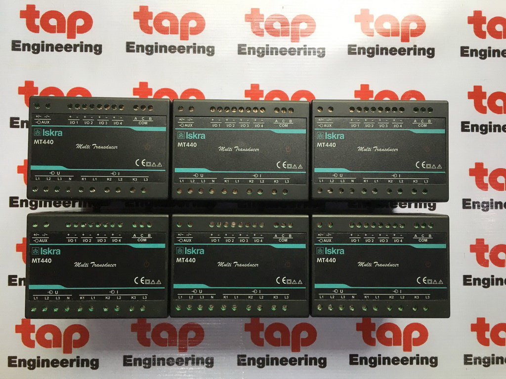
ISKRA MT440
Measuring Transducer
Multifunction Programable Transducer
Manufacturer Part Number : MT440SSUDAAAAA
4 Analog Output, Accuracy Class 0.5
Universal power supply : 24-300Vdc & 48-276Vac, 50-60Hz
Comunication : Serial Port RS485 & USB
Made in Europe


ต้องการสอบถามราคา รายละเอียดสินค้า กรุณาแจ้งยี่ห้อ รุ่น จำนวน เข้ามาที่
Mobile: 091-484-4332
Email: tap.part@engineer.com

ISKRA Sistemi -Measuring Transducer
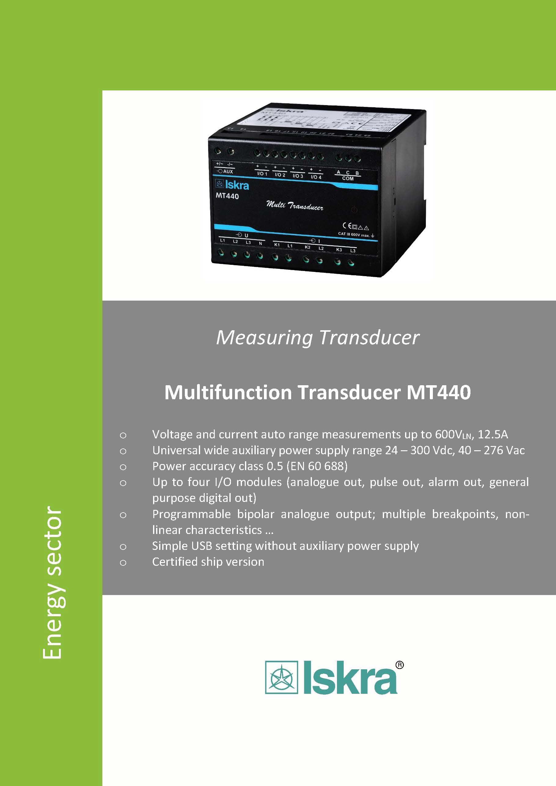
Multifunction Transducer MT440
o Voltage and current auto range measurements up to 600VLN, 12.5A
o Universal wide auxiliary power supply range 24 – 300 Vdc, 40 – 276 Vac
o Power accuracy class 0.5 (EN 60 688)
o Up to four I/O modules (analogue out, pulse out, alarm out, general purpose digital out)
o Programmable bipolar analogue output; multiple breakpoints, non-linear characteristics …
o Simple USB setting without auxiliary power supply
o Certified ship version
Technical Documentation
2 MT440 Multifunction Transducer
PROPERTIES
o Measurements of instantaneous values of more than 50 quantities (V, A, kW, kVA, kvar, kWh, kvarh, PF, Hz, MD thermal, THD, etc)
o Power accuracy class 0.5
o 32 adjustable alarms
o Input frequency: 50/60 Hz, 400 Hz
o Serial communication (RS232 or RS485 up to 115,200 bit/s) and USB 2.0
o MODBUS RTU communication protocol
o Up to 4 I/O (analogue outputs, alarm outputs, pulse outputs, general purpose relay output, general purpose solid-state output)
o Single wide auxiliary power supply range 24 – 300 Vdc, 40 – 276 Vac or fixed AC: 110V, 230V, 400V
o Automatic range of current and voltage (max. 12.5 A and 600 VL-N)
o Housing for DIN rail mounting
o User-friendly setting software, MiQen
DESCRIPTION
MT440 are intended for measuring and monitoring single-phase or three-phase electrical power network. They measure RMS value by means of fast sampling of voltage and current signals, which makes instruments suitable for acquisition of transient events. A built-in microcontroller calculates measurands (voltage, current, frequency, energy, power, power factor, THD phase angles, etc.) from the measured signals.
APPLICATION
The MT440 multifunction transducer is used for measuring and monitoring of all single-phase or three-phase values. Wide range of various I/O modules makes MT440 a perfect choice for numerous applications.
Analogue outputs with fast response.
Alarm (relay) outputs can be used as a supervisory functions with user defined limit lines to all measured parameters.
Precise energy measuring in all 4 quadrants with 4 configurable counters can be used as a secondary energy metering device.
MT440 is delivered un-configured for customer configuration with user friendly setting software MiQen. MT440 supports standard serial communication RS232 or RS485 with speed up to 115200 baud, which is perfect for simple applications and serial bus interfacing.
Additional USB 2.0 interface can only be used for a fast set-up without need for auxiliary power supply. This interface is provided with only BASIC insulation and can be used ONLY unconnected to power inputs.
Special "ship version" is available, certified by Bureau Veritas.
PROGRAMMING
MT440 multifunction transducer is completely programmable. It can be programmed using standard RS232/485 communication (if available) or USB communication (always present). For more information about connection and programming see MT440 Users manual.
Primary-secondary ratio (U, I), alarm limits, energy counter, input and output values are all programmed by setting software MIQen via RS232 or RS485 communication.
It is possible to choose between several standard output value ranges (- 100 … 0 … 100%):
- 10 … 0 … 10 V,
- 1 … 0 … 1 V,
- 20 … 0 … 20 mA,
- 10 … 0 … 10 mA,
- 5 … 0 … 5 mA,
- 1 … 0 … 1 mA,.
Within these six ranges it is possible to set any linear or bent (with maximum 5 break points) output characteristic.
COMPLIANCE WITH STANDARDS: Standard EN Description
61010
Safety requirements for electrical equipment for measurement, control and laboratory use
60688
Electrical measuring transducers for converting AC electrical variables into analogue and digital signals
61326-1
EMC requirements for electrical equipment for measurement, control and laboratory use - Part 1: General requirements
60529
Degrees of protection provided by enclosures (IP code)
60 068-2-1/ -2/ -6/ -27/-30
Environmental testing (-1 Cold, -2 Dry heat, -30 Damp heat, -6 Vibration, -27 Shock)
UL 94
Tests for flammability of plastic materials for parts in devices and appliances
Technical Documentation
MT440 Multifunction Transducer 3
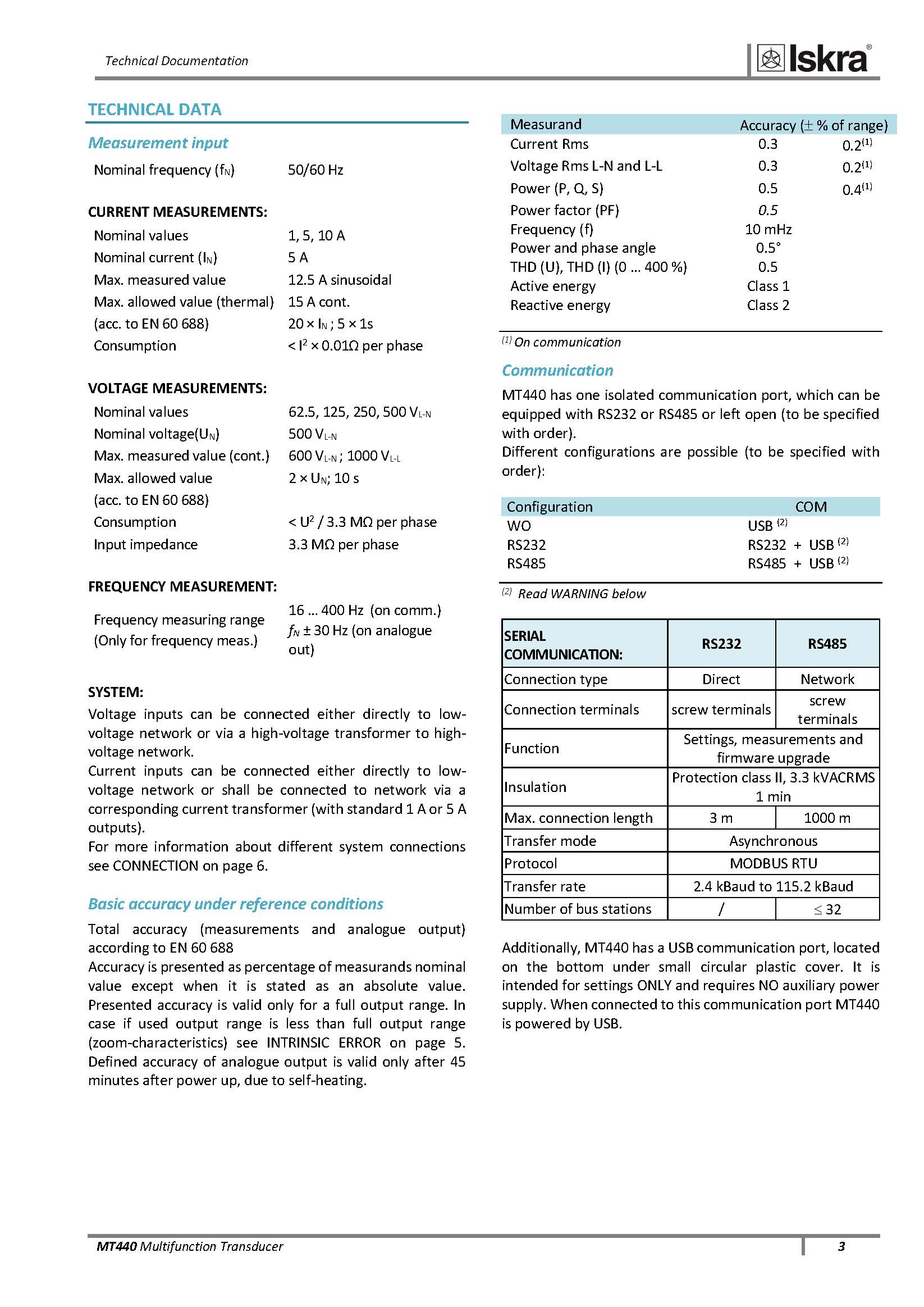
TECHNICAL DATA
Measurement input
Nominal frequency (fN)
50/60 Hz
CURRENT MEASUREMENTS:
Nominal values
1, 5, 10 A
Nominal current (IN)
5 A
Max. measured value
12.5 A sinusoidal
Max. allowed value (thermal)
15 A cont.
(acc. to EN 60 688)
20 × IN ; 5 × 1s
Consumption
< I2 × 0.01Ω per phase
VOLTAGE MEASUREMENTS:
Nominal values
62.5, 125, 250, 500 VL-N
Nominal voltage(UN)
500 VL-N
Max. measured value (cont.)
600 VL-N ; 1000 VL-L
Max. allowed value
2 × UN; 10 s
(acc. to EN 60 688)
Consumption
< U2 / 3.3 MΩ per phase
Input impedance
3.3 MΩ per phase
FREQUENCY MEASUREMENT:
Frequency measuring range
(Only for frequency meas.)
16 … 400 Hz (on comm.)
fN ± 30 Hz (on analogue out)
SYSTEM:
Voltage inputs can be connected either directly to low-voltage network or via a high-voltage transformer to high-voltage network.
Current inputs can be connected either directly to low-voltage network or shall be connected to network via a corresponding current transformer (with standard 1 A or 5 A outputs).
For more information about different system connections see CONNECTION on page 6.
Basic accuracy under reference conditions
Total accuracy (measurements and analogue output) according to EN 60 688
Accuracy is presented as percentage of measurands nominal value except when it is stated as an absolute value. Presented accuracy is valid only for a full output range. In case if used output range is less than full output range (zoom-characteristics) see INTRINSIC ERROR on page 5. Defined accuracy of analogue output is valid only after 45 minutes after power up, due to self-heating.
Measurand Accuracy ( % of range)
Current Rms
0.3
0.2(1)
Voltage Rms L-N and L-L
0.3
0.2(1)
Power (P, Q, S)
0.5
0.4(1)
Power factor (PF)
0.5
Frequency (f)
10 mHz
Power and phase angle
0.5°
THD (U), THD (I) (0 … 400 %)
0.5
Active energy
Class 1
Reactive energy
Class 2
(1) On communication
Communication
MT440 has one isolated communication port, which can be equipped with RS232 or RS485 or left open (to be specified with order).
Different configurations are possible (to be specified with order):
Configuration COM
WO
USB (2)
RS232
RS232 + USB (2)
RS485
RS485 + USB (2)
(2) Read WARNING below
SERIAL COMMUNICATION: RS232 RS485
Connection type
Direct
Network
Connection terminals
screw terminals
screw terminals
Function
Settings, measurements and firmware upgrade
Insulation
Protection class II, 3.3 kVACRMS 1 min
Max. connection length
3 m
1000 m
Transfer mode
Asynchronous
Protocol
MODBUS RTU
Transfer rate
2.4 kBaud to 115.2 kBaud
Number of bus stations
/
32
Additionally, MT440 has a USB communication port, located on the bottom under small circular plastic cover. It is intended for settings ONLY and requires NO auxiliary power supply. When connected to this communication port MT440 is powered by USB.
Technical Documentation
4 MT440 Multifunction Transducer
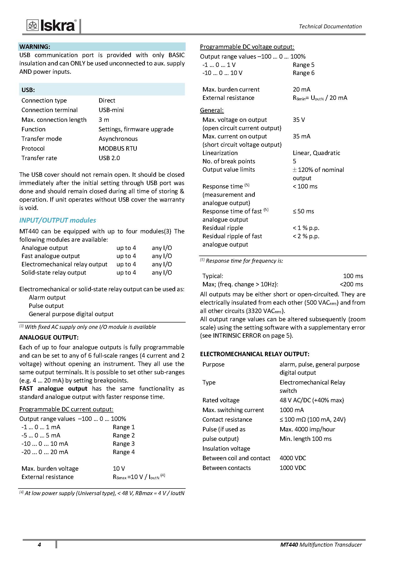
WARNING:
USB communication port is provided with only BASIC insulation and can ONLY be used unconnected to aux. supply AND power inputs.
USB:
Connection type
Direct
Connection terminal
USB-mini
Max. connection length
3 m
Function
Settings, firmware upgrade
Transfer mode
Asynchronous
Protocol
MODBUS RTU
Transfer rate
USB 2.0
The USB cover should not remain open. It should be closed immediately after the initial setting through USB port was done and should remain closed during all time of storing & operation. If unit operates without USB cover the warranty is void.
INPUT/OUTPUT modules
MT440 can be equipped with up to four modules(3) The following modules are available:
Analogue output
up to 4
any I/O
Fast analogue output
up to 4
any I/O
Electromechanical relay output
up to 4
any I/O
Solid-state relay output
up to 4
any I/O
Electromechanical or solid-state relay output can be used as:
Alarm output
Pulse output
General purpose digital output
(3) With fixed AC supply only one I/O module is available
ANALOGUE OUTPUT:
Each of up to four analogue outputs is fully programmable and can be set to any of 6 full-scale ranges (4 current and 2 voltage) without opening an instrument. They all use the same output terminals. It is possible to set other sub-ranges (e.g. 4 … 20 mA) by setting breakpoints.
FAST analogue output has the same functionality as standard analogue output with faster response time.
Programmable DC current output:
Output range values –100 … 0 … 100%
-1 … 0 … 1 mA
Range 1
-5 … 0 … 5 mA
Range 2
-10 ... 0 ... 10 mA
Range 3
-20 ... 0 ... 20 mA
Range 4
Max. burden voltage
10 V
External resistance
RBmax =10 V / IoutN (4)
(4) At low power supply (Universal type), < 48 V, RBmax = 4 V / IoutN
Programmable DC voltage output:
Output range values –100 … 0 … 100%
-1 … 0 … 1 V
Range 5
-10 … 0 … 10 V
Range 6
Max. burden current
20 mA
External resistance
RBmin= UoutN / 20 mA
General:
Max. voltage on output
(open circuit current output)
35 V
Max. current on output
(short circuit voltage output)
35 mA
Linearization
Linear, Quadratic
No. of break points
5
Output value limits
120% of nominal output
Response time (5)
(measurement and
analogue output)
< 100 ms
Response time of fast (5)
analogue output
≤ 50 ms
Residual ripple
< 1 % p.p.
Residual ripple of fast
analogue output
< 2 % p.p.
(5) Response time for frequency is:
Typical:
100 ms
Max; (freq. change > 10Hz):
<200 ms
All outputs may be either short or open-circuited. They are electrically insulated from each other (500 VACrms) and from all other circuits (3320 VACrms).
All output range values can be altered subsequently (zoom scale) using the setting software with a supplementary error (see INTRINSIC ERROR on page 5).
ELECTROMECHANICAL RELAY OUTPUT:
Purpose
alarm, pulse, general purpose digital output
Type
Electromechanical Relay switch
Rated voltage
48 V AC/DC (+40% max)
Max. switching current
1000 mA
Contact resistance
≤ 100 mΩ (100 mA, 24V)
Pulse (if used as
Max. 4000 imp/hour
pulse output)
Min. length 100 ms
Insulation voltage
Between coil and contact
4000 VDC
Between contacts
1000 VDC
Technical Documentation
MT440 Multifunction Transducer 5
SOLID-STATE RELAY OUTPUT
Purpose
alarm, pulse, general purpose digital output
Type
Optocoupler open collector switch
Rated voltage
40 V AC/DC
Max. switching current
30 mA (RONmax = 8Ω)
Pulse length
(if used as pulse output)
programmable (2 … 999 ms)
AUX POWER SUPPLY
UNIVERSAL SUPPLY
Nominal voltage AC range
48 … 276 V
Nominal frequency range
45 … 65 Hz
Nominal voltage DC range
20 … 300 V
Consumption
< 8VA
Power-on transient current
< 20 A; 3 ms
AC supply
Nominal voltage AC
63.5 V, 110 V, 230V, 240 V,
400V
Nominal frequency range
45 … 65 Hz
Consumption
< 5VA
SAFETY:
Protection:
protection class II
Pollution degree
2
Installation category
CAT III; 600 V meas. inputs
CAT III; 300 V aux. uni.supply
CAT III; 600 V aux. AC supply
Acc. to EN 61010-1
Test voltages
UAUXI/O, COM: 5000 VDC
UAUXU, I inputs: 5000 VDC
U, I inI/O,COM: 3320 VACrms
U inI in: 3320 VACrms
Enclosure material
PC/ABS
Acc. to UL 94 V-0
MECHANICAL
Dimensions
W100 × H75× D105 mm
Max. conductor cross section for terminals
2.5 mm2 with pin terminal
4 mm2 solid wire
Vibration withstand
0.7 g, 3 … 100 Hz, 1 oct/min
10 cycles in each of three axes
Shock withstand
300 g, 8 ms pulse
6 shocks in each of three axes
Mounting
Rail mounting 35 × 15 mm
acc. to DIN EN 50 022
Enclosure material
PC/ABS
Flammability
Acc. to UL 94 V-0
Weight
370 g
Enclosure protection
IP 20
ENVIRONMENTAL CONDITIONS:
Ambient temperature
usage group III
- 10 … 0…45 … 55 °C
Acc. to IEC/EN 60 688
(Accuracy outside reference temp. range is not more than 2x class)
Operating temperature
- 30 to + 70 °C
Storage temperature
- 40 to +70 °C
Average annual humidity
93% r.h.
Altitude
2000 m
Technical Documentation
6 MT440 Multifunction Transducer
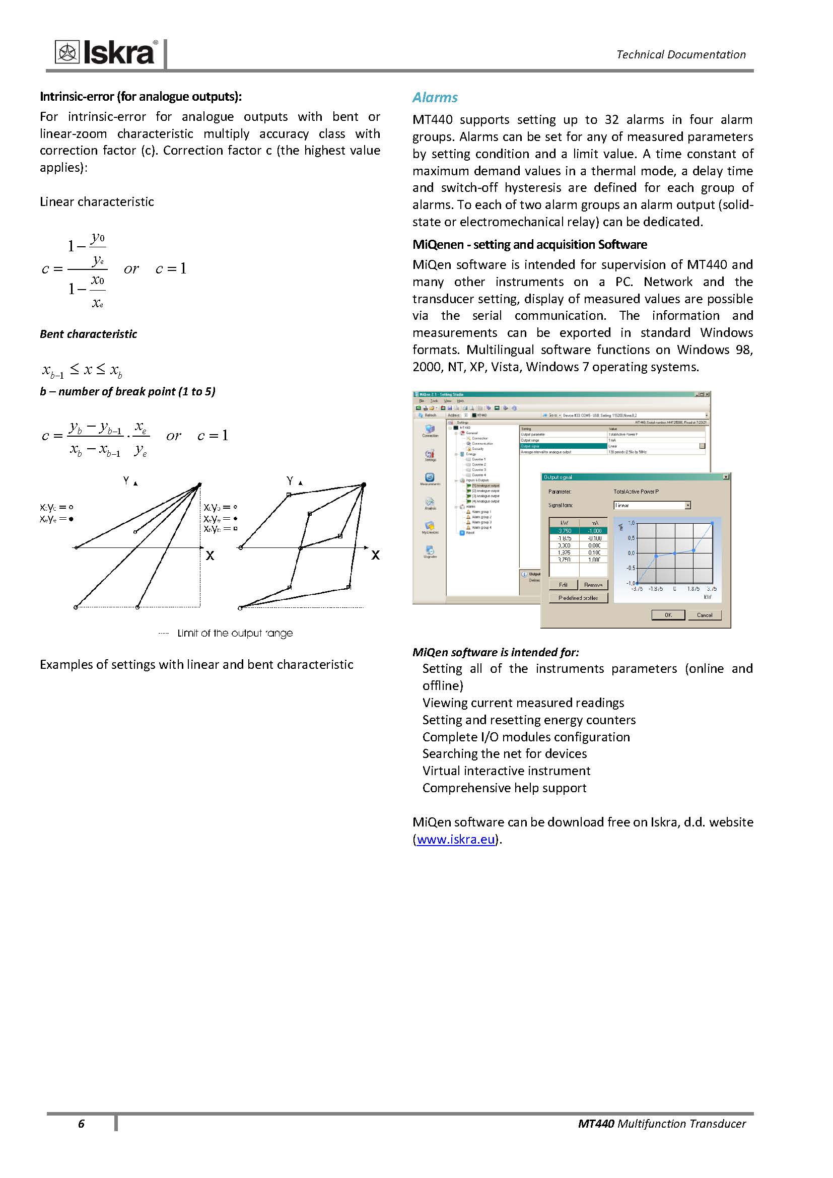
Intrinsic-error (for analogue outputs):
For intrinsic-error for analogue outputs with bent or
linear-zoom characteristic multiply accuracy class with
correction factor (c). Correction factor c (the highest value
applies):
Linear characteristic
1
1
1
0
0
or c
x
x
y
y
c
e
e
Bent characteristic
b b x x x 1
b – number of break point (1 to 5)
1
1
1
or c
y
x
x x
y y
c
e
e
b b
b b
Examples of settings with linear and bent characteristic
Alarms
MT440 supports setting up to 32 alarms in four alarm
groups. Alarms can be set for any of measured parameters
by setting condition and a limit value. A time constant of
maximum demand values in a thermal mode, a delay time
and switch-off hysteresis are defined for each group of
alarms. To each of two alarm groups an alarm output (solidstate
or electromechanical relay) can be dedicated.
MiQenen - setting and acquisition Software
MiQen software is intended for supervision of MT440 and
many other instruments on a PC. Network and the
transducer setting, display of measured values are possible
via the serial communication. The information and
measurements can be exported in standard Windows
formats. Multilingual software functions on Windows 98,
2000, NT, XP, Vista, Windows 7 operating systems.
MiQen software is intended for:
Setting all of the instruments parameters (online and
offline)
Viewing current measured readings
Setting and resetting energy counters
Complete I/O modules configuration
Searching the net for devices
Virtual interactive instrument
Comprehensive help support
MiQen software can be download free on Iskra, d.d. website
(www.iskra.eu).
Technical Documentation
MT440 Multifunction Transducer 7
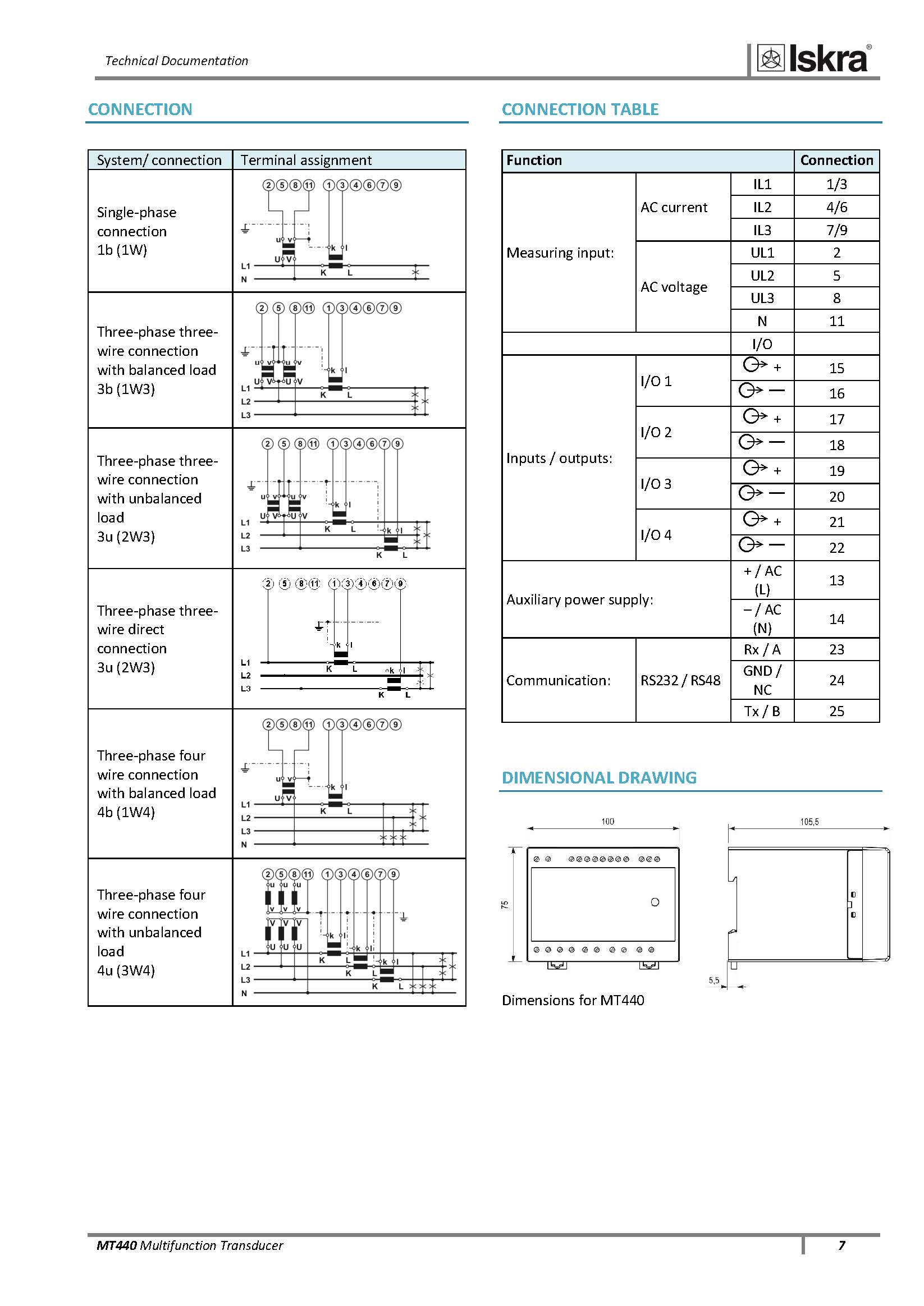
CONNECTION
System/ connection Terminal assignment
Single-phase connection
1b (1W)
Three-phase three-wire connection with balanced load
3b (1W3)
Three-phase three-wire connection with unbalanced load
3u (2W3)
Three-phase three-wire direct connection
3u (2W3)
Three-phase four wire connection with balanced load
4b (1W4)
Three-phase four wire connection with unbalanced load
4u (3W4)
CONNECTION TABLE
Function Connection
Measuring input:
AC current
IL1
1/3
IL2
4/6
IL3
7/9
AC voltage
UL1
2
UL2
5
UL3
8
N
11
I/O
Inputs / outputs:
I/O 1
+
15
16
I/O 2
+
17
18
I/O 3
+
19
20
I/O 4
+
21
22
Auxiliary power supply:
+ / AC (L)
13
– / AC (N)
14
Communication:
RS232 / RS48
Rx / A
23
GND / NC
24
Tx / B
25
DIMENSIONAL DRAWING
Dimensions for MT440
Technical Documentation
8 MT440 Multifunction Transducer
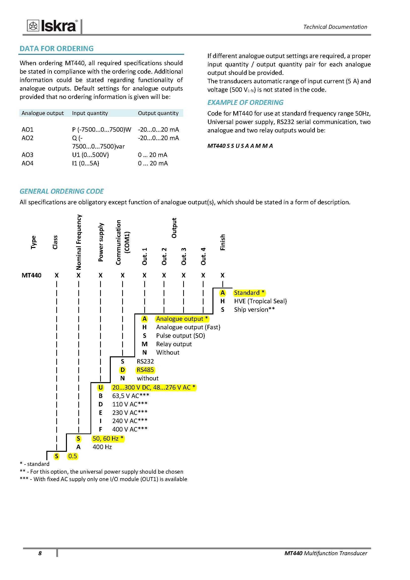
DATA FOR ORDERING
When ordering MT440, all required specifications should be stated in compliance with the ordering code. Additional information could be stated regarding functionality of analogue outputs. Default settings for analogue outputs provided that no ordering information is given will be:
Analogue output Input quantity Output quantity
AO1
P (-7500...0...7500)W
-20...0...20 mA
AO2
Q (-7500...0...7500)var
-20...0...20 mA
AO3
U1 (0...500V)
0 … 20 mA
AO4
I1 (0...5A)
0 ... 20 mA
If different analogue output settings are required, a proper input quantity / output quantity pair for each analogue output should be provided.
The transducers automatic range of input current (5 A) and voltage (500 VL-N) is not stated in the code.
EXAMPLE OF ORDERING
Code for MT440 for use at standard frequency range 50Hz, Universal power supply, RS232 serial communication, two analogue and two relay outputs would be:
MT440 S S U S A A M M A
GENERAL ORDERING CODE
All specifications are obligatory except function of analogue output(s), which should be stated in a form of description.
Type
Class
Nominal Frequency
Power supply
Communication
(COM1)
Output
Finish
Out. 1
Out. 2
Out. 3
Out. 4
MT440
X
X
X
X
X
X
X
X
X
|
|
|
|
|
|
|
|
|
|
|
|
|
|
|
|
|
A
Standard *
|
|
|
|
|
|
|
|
H
HVE (Tropical Seal)
|
|
|
|
|
|
|
|
S
Ship version**
|
|
|
|
A
Analogue output *
|
|
|
|
H
Analogue output (Fast)
|
|
|
|
S
Pulse output (SO)
|
|
|
|
M
Relay output
|
|
|
|
N
Without
|
|
|
S
RS232
|
|
|
D
RS485
|
|
|
N
without
|
|
U
20...300 V DC, 48...276 V AC *
|
|
B
63,5 V AC***
|
|
D
110 V AC***
|
|
E
230 V AC***
|
|
I
240 V AC***
|
|
F
400 V AC***
|
S
50, 60 Hz *
|
A
400 Hz
S
0.5
* - standard
** - For this option, the universal power supply should be chosen
*** - With fixed AC supply only one I/O module (OUT1) is available
Printed in Slovenia Subject to change without notice Version 3.02 / Sep-2018 GB P 22.496.500


ระบบสมาชิก
DHL Express

FedEx Express

TNT Express

UPS Tracking

USPS Tracking

KERRY Express

EMS & Thailandpost Tracking


▲
▼
รายการสั่งซื้อของฉัน
รายการสั่งซื้อของฉัน
ข้อมูลร้านค้านี้

บริษัท ทีเอพี พาร์ท เอ็นจิเนียริ่ง จำกัด
บ.ทีเอพี พาร์ทฯ ก่อตั้งขึ้นเมื่อปี 2551 โดยกลุ่มวิศกรที่มีประสบการณ์ เราจำหน่าย-เป็นผู้นำเข้าสินค้าเองโดยตรงจากต่างประเทศ อาทิ เครื่องจักร อะไหล่วิศวกรรม อุปกรณ์ไฟฟ้าคอนโทรล เครื่องมือวัด และอุปกรณ์ต่างๆที่ใช้ในทุกกลุ่มอุตสาหกรรม ต่อมาด้วยประสบการณ์ต่างๆ เราสามารถขยายธุรกิจโดยการเป็นตัวแทนจำหน่าย รวมถึงบริการติดตั้งโครงการระบบควบคุมและสั่งการอุปกรณ์ไฟฟ้า
เบอร์โทร : 091-484-4332
อีเมล : info@tap-part.com
อีเมล : info@tap-part.com
ส่งข้อความติดต่อร้าน
เกี่ยวกับร้านค้านี้
ค้นหาสินค้าในร้านนี้
ค้นหาสินค้า
สินค้าที่ดูล่าสุด
บันทึกเป็นร้านโปรด
Join เป็นสมาชิกร้าน
แชร์หน้านี้
แชร์หน้านี้
↑
TOP เลื่อนขึ้นบนสุด
TOP เลื่อนขึ้นบนสุด
สินค้าในตะกร้า ({{total_num}} รายการ)

ขออภัย ขณะนี้ยังไม่มีสินค้าในตะกร้า
ราคาสินค้าทั้งหมด
฿ {{price_format(total_price)}}
- ฿ {{price_format(discount.price)}}
ราคาสินค้าทั้งหมด
{{total_quantity}} ชิ้น
฿ {{price_format(after_product_price)}}
ราคาไม่รวมค่าจัดส่ง
รวมภาษีมูลค่าเพิ่มแล้ว
➜ เลือกซื้อสินค้าเพิ่ม