ISKRA #Europe
3 เดือนที่ผ่านมา
ISKRA
Product of Europe
TAP Part Engineering Co., Ltd.
Company in Thailand

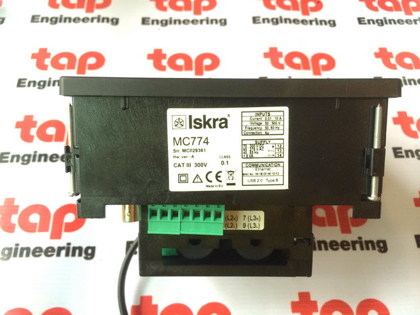
"ISKRA" MC774
"ISKRA" Energy Meter


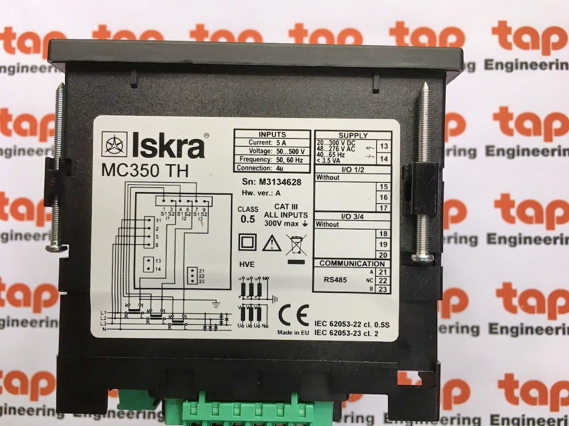
Multimeter MC350TH
"ISKRA" Energy Meter


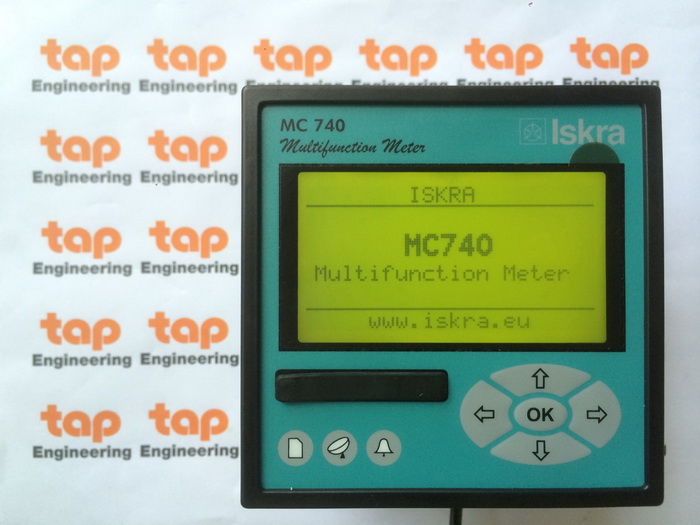
Multifunction Meter
Model: MC740


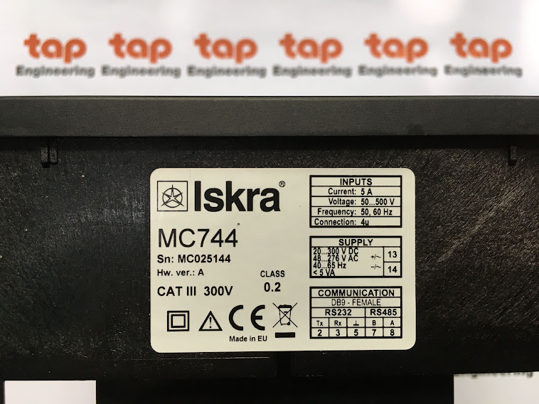
ISKRA MC744 Multifunction Meter

ISKRA MC750 Network Recorder


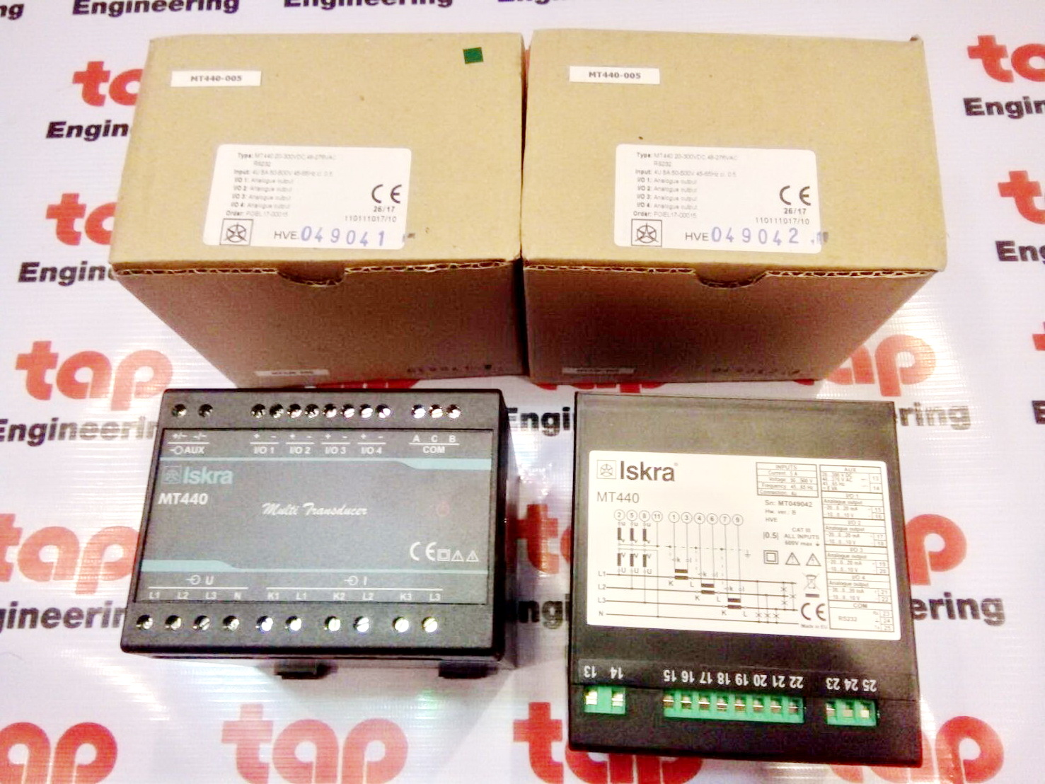
Measuring Transducer Multifunction Transducer
ISKRA MT440


ISKRA - Programmable Voltage Transducer
MT416
Programmable AC Current Transducer
Model: MT418


Multifunction Transducer, Class 0.1
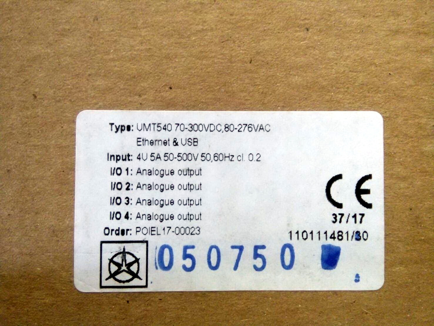
Model: UMT540


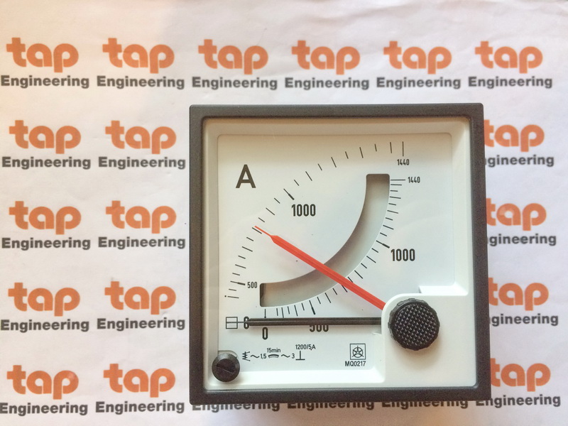
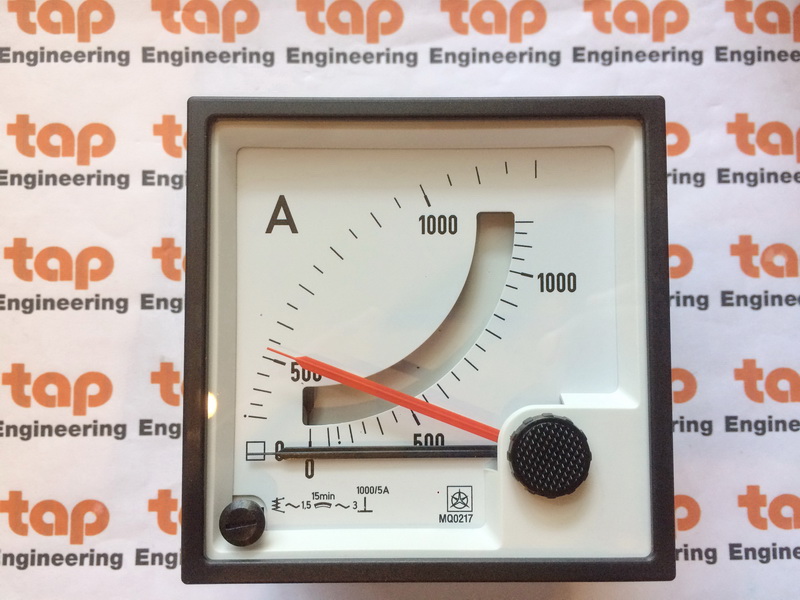
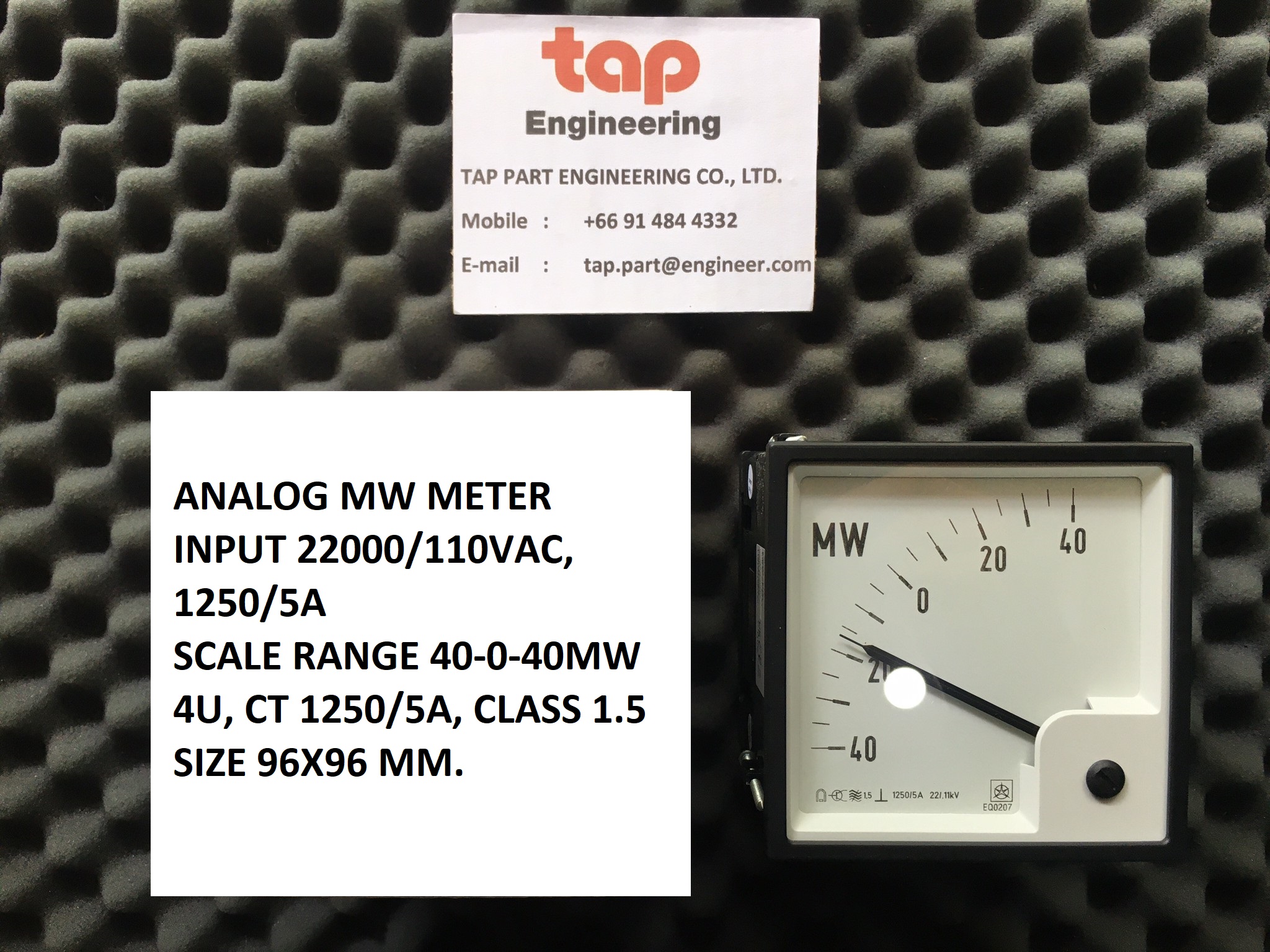
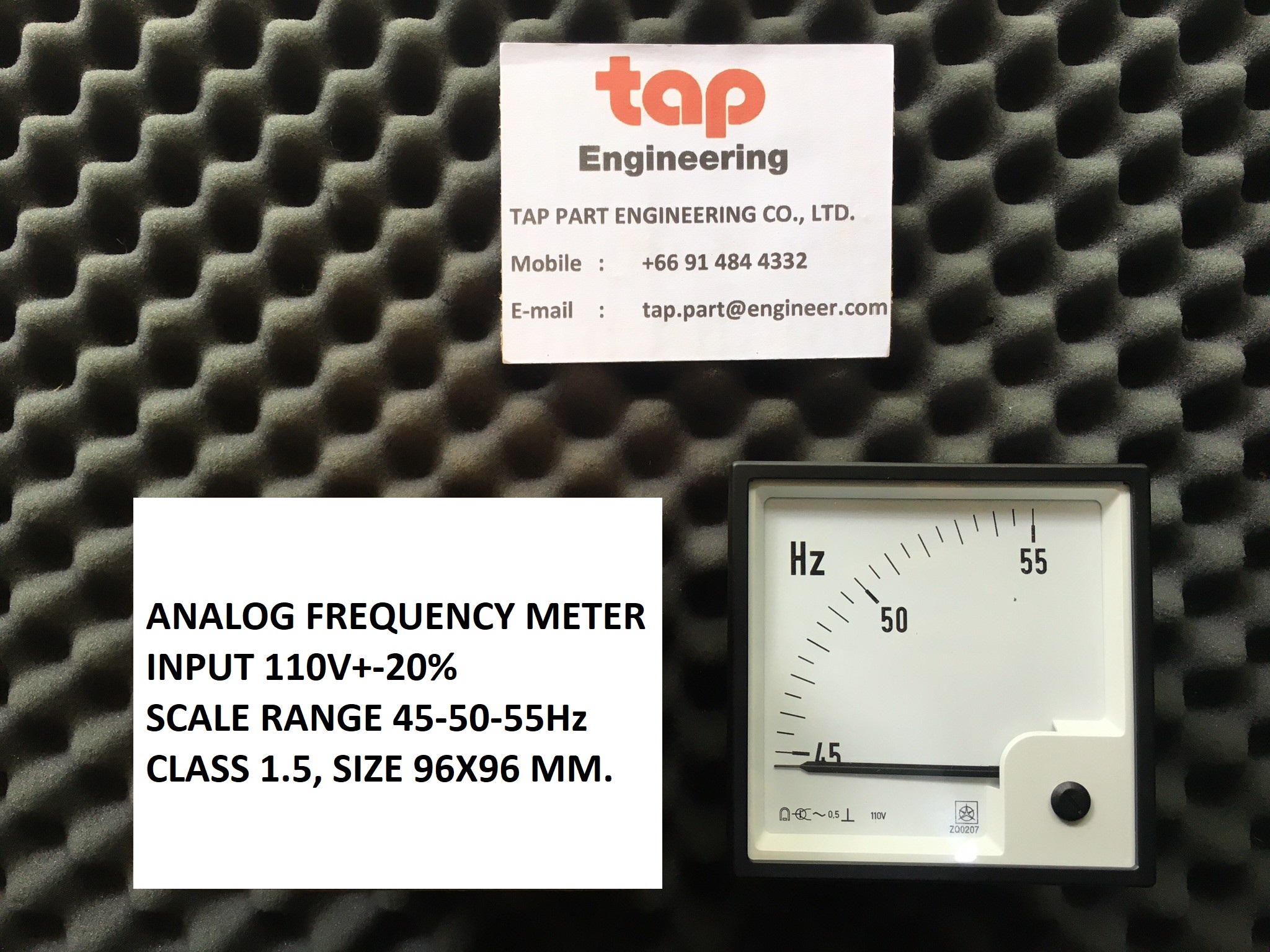
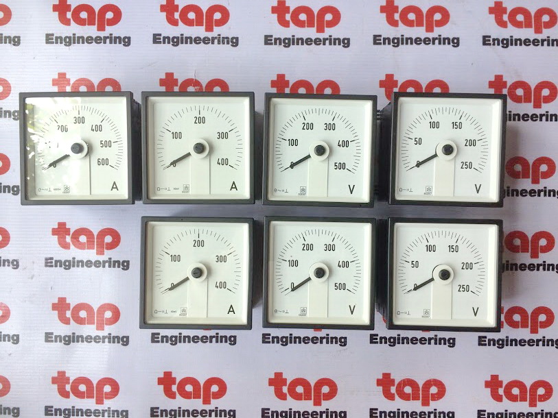
Analog Panel Meter


Product of "ISKRA"
Product of Europe
TAP Part Engineering Co., Ltd.
Company in Thailand
Contact us: tap.part@engineer.com
Mobile: 091-4844332"ISKRA" MC774
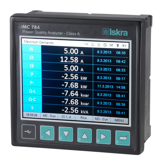
PQM Power Quality Meter, Power Monitoring Unit
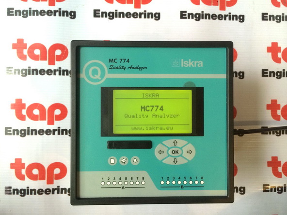
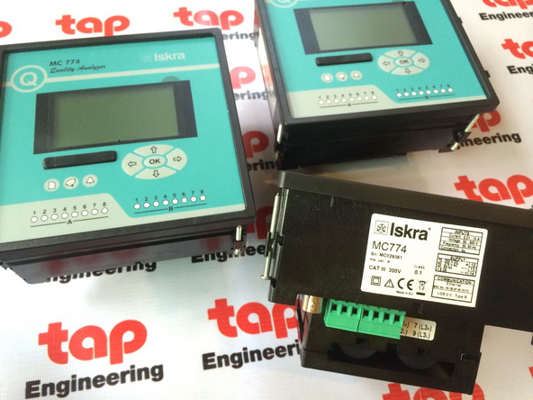
Power Quality Analyzer Meter
iMC784 "ISKRA"
5.7" color display


Multimeter MC330Multimeter MC350TH
Multifunction Meter
Model: MC740
ISKRA MC744 Multifunction Meter
ISKRA MC750 Network Recorder
Ordering Code: MC750 : EDC/AC-RS-2AN-2PO-2GB
Measuring Transducer Multifunction Transducer
ISKRA MT440
ISKRA - Programmable Voltage Transducer
MT416
Programmable AC Current Transducer
Model: MT418
Multifunction Transducer, Class 0.1
Model: UMT540
ISKRA MI450
Programmable transducers for RTD sensors
Measuring transducer MI450, for Pt100 RTD sensor
with temperature range 0…100 C, output range 4…20 mA, 4-wire connection
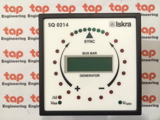
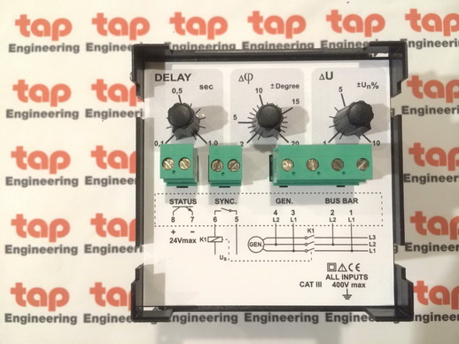
ISKRA SQ0214 SYNCHRONIZATION METERS
INPUT 400 VL-L , Continuous Relay O/P
45-65 Hz, Dead Busbar function 20% Un , Status O/P , +/-2…20 el.
Analog Panel Meter
Moving-coil Panel instruments
AMMETERS
VOLTMETER
uA
mA
mV
A
kW
kW
Ohm
AC
DC
0-100%
0-100%
4-20
Product of "ISKRA"
MC330 Multimeter
MC350 Network recorder
MT440 Measuring transducers
MT540/UMT540 Multifunction Transducer
MI450 Temperature with Pt 100 Transducer
MI452 Resistance Transducer
MI454 TAP position Transducer
MI456 DC voltage Transducer
MC750/UMC750 Network Recorder
MT540/UMT540 Multifunction Transducer
MI450 Temperature with Pt 100 Transducer
MI452 Resistance Transducer
MI454 TAP position Transducer
MI456 DC voltage Transducer
MI458 DC current Transducer
MC740/UMC740 Power monitoring deviceMC750/UMC750 Network Recorder
MC760/UMC760 Network Analyzer
MC774 Quality Analyser - Class A
iMC784, MC784 Advanced Power Quality Analyser
DM3xx DIGITAL METER
BQ0407 Analog panel meter
EQ0207 YQ0207 Analogue Meters
FQ0x07 Analogue Meters
SQ0214 SQ0204 Synchronization Meters
- CapacitorsDM3xx DIGITAL METER
BQ0407 Analog panel meter
EQ0207 YQ0207 Analogue Meters
FQ0x07 Analogue Meters
SQ0214 SQ0204 Synchronization Meters
- Low Voltage Switchgear
- Electrical Measuring Instruments
- Power Automation and Protection
- Professional Batteries
- Cores
- Antenna Systems
- Potentiometers
- Telecommunications
- Software
- etc.
- etc.
ต้องการสอบถามราคา รายละเอียดสินค้า กรุณาแจ้งยี่ห้อ รุ่น จำนวน เข้ามาที่
Mobile: 091-484-4332
Email: tap.part@engineer.com
ISKRA EX104
ISKRA FPC200-B2
ISKRA FPC200-F3
ISKRA FPC200-M3
ISKRA FPC200-T3
ISKRA FPC400-B3
ISKRA FPC400-F3
ISKRA FPC400-F4
ISKRA FPC400-G4
ISKRA FPC400-M4
ISKRA FPC400-T4
ISKRA iMC784
ISKRA MC320
ISKRA MC330
ISKRA MC350
ISKRA MC350H
ISKRA MC640
ISKRA MC646
ISKRA MC650
ISKRA MC656
ISKRA MC660
ISKRA MC666
ISKRA MC710
ISKRA MC720
ISKRA MC740
ISKRA MC744
ISKRA MC750
ISKRA MC754
ISKRA MC760
ISKRA MC764
ISKRA MC774
ISKRA MC784
ISKRA MI400
ISKRA MI401
ISKRA MI404
ISKRA MI413
ISKRA MI414
ISKRA MI416
ISKRA MI418
ISKRA MI420
ISKRA MI421
ISKRA MI436
ISKRA MI438
ISKRA MI450
ISKRA MI452
ISKRA MI454
ISKRA MI456
ISKRA MI458
ISKRA MI7140
ISKRA MI7150
ISKRA MT416
ISKRA MT418
ISKRA MT440
ISKRA MT510
ISKRA MT511
ISKRA MT516
ISKRA MT518
ISKRA MT540
ISKRA MT550
ISKRA MT560
ISKRA RD500
ISKRA SR100
ISKRA UMC710
ISKRA UMC720
ISKRA UMC740
ISKRA UMC750
ISKRA UMC760
ISKRA UMT510
ISKRA UMT511
ISKRA UMT516
ISKRA UMT518
ISKRA UMT540
ISKRA UMT550
ISKRA UMT560
ISKRA WM1-6
ISKRA WM1-6Z
ISKRA WM1M6
ISKRA WQ0207
ISKRA WQ0217
ISKRA WS0101
ISKRA WS0102
ISKRA WS0301
ISKRA WS0302
ISKRA WS1102
ISKRA WS1302
Electrical Measuring
Instruments
®
Index
1
Contents: Page
Measuring Centres
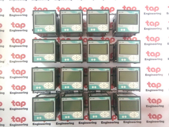
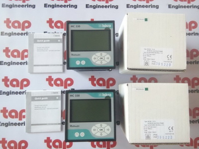
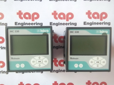
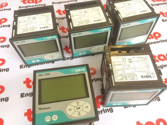
MC 320 − Energy meter, MC 330 − Multimeter 3
MC 760/UMC 760 − Network Analyzer, MC 750/UMC 750 - Network Recorder 5
MC 740 − Multifunction Meter 7
MC 744 − Multifunction Meter, MC 754 − Network Recorder, MC 764 − Network Analyzer 9
MC 660/MC 666 − Network Analyzer for Rail Mounting 12
MC 650/MC 656 − Network Recorder for Rail Mounting 13
MC 640/MC 646 − Multifunction Meter for Rail Mounting 14
Measuring Transducers
MT 5x0/UMT 5x0 Measuring Transducers 15
MT 560/UMT 560 − Transducer & Analyser 17
MT 550/UMT 550 − Transducer & Recorder 18
MT 540/UMT 540 − Multifunction Transducer 18
RD 500 − Remote Display for Measuring Transducers MT 5x0/UMT 5x0 19
MT 510/UMT 510 - Power Transducer 20
MT 511/UMT 511 - Power Transducer & Recorder 21
MT 516/UMT 516 - Voltage Transducer 22
MT 518/UMT 518 - Current Transducer 23
MT 406 - AC Voltage self powered Transducers 24
MT 408 - AC Current self powered Transducers 25
MT 416 - Programmable AC Voltage Transducers 26
MT 418 - Programmable AC Current Transducers 27
MT 440 - Multifunctional Transducers 28
MT 4xx - Measuring Transducers 29
MIBOX - Communicators 30
MIQEN 32
MISMART 34
Communication Adapters
MI 480 − GSM Device for remote control 36
MI 485 − RS 232 / RS 485 Interface 38
MI 486, MI 488 − Interface TCP / IP 39
Digital Meters
Digital Meters with LED Display 40
Synchronization Meters 42
Energy Meters with Power Display 43
Hour Meters & Pulse Countres
Hour Meters HK 30 - HK 49 44
Pulse Counters SI 63, SI 64, SI 65, MC 703, MC 723 45
Index
2
Analogue Meters
Active or Reactive Power Meters 46
Power Factor Meters 47
Pointer Frequency Meters 48
Reed Frequency Meters 49
Meter with Limit Contact 50
Meters for DC Voltage or Current with Moving Coil 51
TAP Position Meters with Moving Coil 52
Meters for AC Voltage or Current with Moving Coil and a Rectifier 54
Meters for DC Voltage or Current with Moving Coil 55
Meters for AC Voltage or Current with Moving Iron 56
Bimetal Maximum Current Meters 58
Combined Bimetal Maximum Current Meters 59
Phase Sequence Indicator and Temperature Meters 60
Portable Meters
MI 7033 Analogue Multiwattmeter 61
Multimeters 62
Educational Programme 63
M I 7022 Digital Temperature Meter 64
Equipment and Accessories
Shunts 65
Current Measuring Transformers 66
Special Demands 67
General Explanations 68
Dimensional Drawings 72
Conection Diagrams 87
Instruments Conformity to Standards 105
NOTE:
Data about ENERGY METERS can be found in separate brochure.
3
Measuring Centres
USE
For electricity distribution and energy production
companies, utilities, dwellings, energy management
solution providers, industry, business buildings, designers
of small power stations, panel builders, etc.
Main features are:
• Measurements of instantaneous values for more than
60 quantities (U, I, P, Q, S, PF, PA, f, j, THD, MD …)
• 4 Energy counters
• Accuracy class U, I, P 0.5 (Active energy Class 1)
• Large frequency range from 16 2/3 Hz to 400 Hz
• Up to 2 tariff inputs (option)
• Up to 2 pulse or relay outputs (option)
• AC or Universal (option) power supply
• Graphical LCD; 128 x 64 dots with illumination
• Automatic range of nominal current (max. 12.5 A) and
voltage (option)
• User-adjustable display of measurements
• Multilingual support (13 languages)
• RS 485 or RS232 communication up to 115,200 bit/s
(option)
• MODBUS communication protocol supported
• User-friendly PC MiQen software for setting via
Measurands RS485 or RS232 communication
• RMS values of currents and voltages (only MC330)
• Measurements of active, reactive, apparent power and power factor (only MC330)
• Measurements of energy in all 4 quadrants
• Average values of measurands per interval (only MC330)
Input / output modules
The modules are available with double inputs/outputs. Each module has three terminals. The meter is available without,
with one or with two modules. The following modules are available:
• Output module (relay version MC330 only) 2 outputs
• Tariff input 2 inputs
Output module is available as:
• Opto output according EN62053-31:2001 (27 V, 27 mA)
• Relay output in MC330 can be used for pulse output or alarm output (40 V, 1 A).
Communication
Option is communication module for reading measured val-ues and instrument setting. Available is RS232 or RS485
communication type module. Communication is galvanic separated from other circuits. For setting we suggest using
MIQEN software.
Supply
Standard is AC power supply enables connection of the meter to AC voltage (57.7 & 63.5 / 100 & 110 / 230 / 400).Option
is a universal power supply enables connection of the meter to DC (20−300 V) or AC voltage (48−276 V / 50 Hz).
MiQEN
MiQen software is intended for supervision of the meter on PC. It enables setting meter parameters that are transferred
into the instrument via communication (option). Multilingual software functions on Windows 98, 2000, NT, XP
operating systems.
MC 320 - Energy Meter , MC 330 - Multimeter
Measuring Centres
4
Multimeter MC 330, Energy Meter MC 320
Accuracy
Accuracy is presented as percentage from nominal value of the measurand except when it is stated as an
absolute value.
Measurand Accuracy
Rms current (I1, I2, I3, lavg, In, MD) 0.5
Rms phase voltage (U1, U2, U3, Uavg, MD) 25 … 600 V 0.5
Phase-to-phase voltage (U12, U23, U31, Uavg) 0.5
Frequency (f) 10 mHz
Power factor (PF) 0.5
Phase and phase-to-phase angle (ϕ, ϕ12, ϕ23, ϕ31) 0.5°
Active, reactive and apparent power 0.5
Active energy EN 62053-21 Class 1
Reactive energy EN 62053-23 Class 2
Pulse output EN 62053-31 Class A & B
Inputs
Inputs signals Current Voltage
Nominal frequency range 50, 60 Hz
Measuring frequency range 16 - 400 Hz
Nominal value (In, Un) 1 / 5 A 75, 120, 250, 500 VL-N
Maximal value 12.5 A 600 VL-N
Consumption < 0.1 VA < 0.1 VA
Power supply
Power supply Universal AC
Nominal voltage AC 48 - 276 V 57.7 & 63.5 / 100 & 110 / 230 / 400
Nominal frequency 40 - 65 Hz 40 - 65 Hz
Nominal voltage DC 20 - 300 V —
Consumption < 3 VA < 3 VA
Safety
Safety
Protection clas II
600 v rms, installation category II
300 v rms, installation category III
Pollution degree 2
in compliance with EN 61010-1:2002
Enclosure material PC/ABS Incombustibility-self-extinguish ability, complying with UL 94 V-0
Enclosure protection IP 52 (IP 00 for terminals) in compliance with EN 60529:1997
Reference conditions
Ambient temperature -10 … 23 … 55 °C
Voltage input +/- 20 % Un
Voltage input with voltage autorange 50 … 500 V
Current input 0 … 100 % In
Active/reactive power factor cos ϕ = 1 / sin ϕ
Waveform sinus
Ambient conditions
Temperature range of operation -10 to +55 °C
Storage temperature range -40 to +70 °C
Average annual humidity ≤ 75 % r.h.
Dimensional drawings on page 82.
Connection diagrams on pages 87.
Software on pages 32-35.
Measuring Centres
5
Main features are:
• Evaluation of the quality of electric voltage in compliance with EN 50160 (only MC 760/UMC 760)
• Measurements of instantaneous values of more than 140 quantities (U, I, P, Q, S, PF, PA, f, ϕ, THD, MD,
energy, energy price by tariffs, etc.).
• Accuracy class 0.5
• Harmonic analysis of phase, phase-to-phase voltages and currents up to the 63th harmonic (only MC 760/
UMC 760)
• Recording up to 32 measured quantities and alarms in the internal memory (8 MB flash - MC 760/UMC 760,
4 MB flash - MC 750/ 750)
• Measurements of 40 minimal and maximal values in different time periods
• 32 adjustable alarms
• Wide frequency range from 16 Hz to 400 Hz
• RS 232/RS 485 communication up to 115,200 bit/s or Ethernet communication
• MODBUS and DNP3 communication protocol
• MMC memory card for data transmission, setting and upgrading
• Up to 4 inputs or outputs (analogue outputs, pulse outputs, alarm outputs, tariff inputs, pulse input, analogue input,
bistable alarm, digital input)
• Universal or AC power supply
• Graphical LCD 128 x 64 dots with illumination
• Automatic range of nominal current up to 5 A and nominal voltage up to 500 V
• Adjustable tariff clock, display of electric energy consumption in optional currency
• Multilingual support
• User-friendly PC MiQen software
MC 760/UMC 760 - NETWORK ANALYZER,
MC 750/UMC 750 - NETWORK RECORDER
USE
The MC 760/UMC 760 network analyzer is used for
permanent analysis of electric voltage quality in compliance
with the EN 50160 standard. Records are
stored in the internal memory for the period of the last
3 years. Moreover, more than 170,000 deviations of
the measured quantities from the standard values are
stored, which enables finding of eventual reasons for
the problems on network. Optional limits and required
quality in a monitored period can be defined for each
monitored characteristic.
The meter measures and records the following
characteristics:
• Frequency deviations
• Voltage deviations
• Voltage dips
• Voltage interruptions
• Voltage unbalances
• Over-voltages
• Fast voltage changes
• Flicker intensity
• THD
• Harmonics
Measuring Centres
6
Handling the costs
A special meter function is cost evaluation of energy (active, reactive and total) by tariffs. The meter itself enables tracing
the energy costs in optional currency. The meter calculates consumption in optional currency by means of the adjustable
tariff clock and electric energy price.
Input / output modules
The modules are available with double inputs/outputs using a common connection contact (except a bistable alarm
module - 1 output, 3 terminals). The meter is available without, with one or with two modules. The following modules
are available:
• Alarm output 2 outputs
• Analogue output 2 x 20 mA outputs
• Pulse output 2 outputs
• Tariff input 2 inputs
• Bistable alarm output 1 output
• Additional communication port (COM2)
• Pulse input
• Analogue Input
• Digital input
Dimensional drawings on page 82.
Connection diagrams on pages 88,89.
Software on pages 32-35.
MC 760/UMC 760 - NETWORK ANALYZER,
MC 750/UMC 750 - NETWORK RECORDER
Measuring Centres
7
USE
The MC 740 multifunction meter is used for
monitoring and measuring electrical quantities of
a three-phase electric-energy distribution system.
The meter is provided with 32 program adjustable
alarms, up to four inputs or outputs and
communication. The meter can be set and measurements
can be checked with the RS 232/RS
485 or Ethernet communication. The meter also
functions as an electricity meter, with the additional
function of cost management by tariffs. A
tariff input or a tariff clock can be set. At tariff
clock setting, four periods and four work groups
as well as electric energy price for each period
and a work group (16 different price periods) are
available. Additionally, 20 places are available for
setting holidays or days when special tariff rules are
valid. As an electricity meter it records energy in all
four quadrants in four tariffs.
Main features are:
• Measurement of instantaneous values of more than 130 quantities
(U, I, P, Q, S, PF, PA, f, ϕ, MD, energy, energy price by tariffs, etc.).
• Accuracy class 0.5
• Measurement of 40 minimum and maximum values in different time periods
• 32 adjustable alarms
• Wide frequency range from 16 Hz to 400 Hz
• RS 232/RS 485 communication up to 115,200 bit/s or Ethernet communication
• MODBUS and DNP3 communication protocols
• MMC memory card for setting and upgrading the meter
• Up to 4 inputs or outputs (analogue outputs, pulse outputs, alarm outputs, tariff inputs, pulse input, analogue input,
bistable alarm, digital input)
• Universal or AC power supply
• Graphic LCD 128 x 64 dots with illumination
• Automatic range of nominal current up to 5 A and nominal voltage up to 500 V
• Adjustable tariff clock, display of electric energy consumption in optional currency
• Multilingual support
• User-friendly PC MiQen software
MC 740/UMC 740 - Multifunction meter
Measuring Centres
8
Handling the costs
A special meter function is cost evaluation of energy (active, reactive and total) by tariffs. The meter itself enables tracing
the energy costs in optional currency. The meter calculates consumption in optional currency by means of the adjustable
tariff clock and electric energy price.
Input / output modules
The modules are available with double inputs/outputs using a common connection contact (except a bistable alarm
module - 1 output, 3 terminals). The meter is available without, with one or with two modules. The following modules are
available:
• Alarm output 2 outputs
• Analogue output 2 x 20 mA outputs
• Pulse output 2 outputs
• Tariff input 2 inputs
• Bistable alarm output 1 output
• Pulse input
• Analogue Input
• Digital input
Dimensional drawings on page 82.
Connection diagrams on pages 88,89.
Software on pages 32-35.
MC 740/UMC 740 - Multifunctionmeter
Measuring Centres
9
MC 764 - NETWORK ANALYZER, MC 754 - NETWORK
RECORDER, MC 744 - MULTIFUNCTION METER
DESCRIPTION
The meter is intended for measuring, analysing and
monitoring single-phase or three-phase electrical power
network. The meter measures RMS value according
to the principle of fast sampling of voltage and current
signals. A built-in microprocessor calculates measurands
(voltage, current, frequency, energy, power, power factor,
THD phase angles, etc.) from the measured signals.
USE
Meters from MC7x4 series are designed for
environments where beside measurement of threephase
electrical power network additional analogue or
digital measurements/controls must be made without
additional hardware (PLC, OPLC, ...). Meters are housed
in enclosure 144mm x 144mm.
Features:
• Alarm or relay outputs
• Digital inputs/outputs
• Analogue outputs/inputs
• Evaluation of the electricity supply quality in compliance with EN 50160 (only MC 764)
• Measurements of instantaneous values of more than 140 quantities (U, I, P, Q, S, PF, PA, f, ϕ, THD, MD,
energy, energy cost by tariffs, etc.)
• Accuracy class 0.5 (optional 0.2)
• Harmonic analysis of phase, phase-to-phase voltages and currents up to the 63rd harmonic (only MC 764)
• Recording up to 32 measurands and 32 alarms in the internal memory (only MC 754/764)
• Measurements of 40 minimal and maximal values in different time periods
• 32 adjustable alarms
• Frequency range from 16 Hz to 400 Hz
• RS 232/RS 485 communication up to 115,200 bit/s or Ethernet & USB communication
• MODBUS and DNP3 communication protocol
• MMC/SD card for data transmission, setting and upgrading
• Up to 4 inputs or outputs (analogue outputs, pulse outputs, alarm outputs, tariff inputs, pulse input, analogue input,
bistable alarm, digital input)
• Additional I/O modules with up to 16 digital inputs or outputs, or up to 8 analogue outputs
• Additional communication port (COM2)
• Universal power supply
• Graphical LCD; 128 x 64 dots with illumination
• Automatic range of nominal current and voltage (max. 12.5 A and 750 V)
• Adjustable tariff clock, display of electric energy consumption in optional currency
• Multilingual support
• User-friendly PC MiQen software
• Additional analogue or digital measurements/controls can be made without additional hardware (PLC, OPLC, etc.)
Dimensional drawings on page 82.
Connection diagrams on pages 90.
Software on pages 32-35.
Measuring Centres
10
Familyof MC 7x0/UMC 7x0, MC 7x4
- Comparisonandcommoncharacteristics
Instrument
DIN 96 MC 744 MC 754 MC 764 MC 740 MC 750 MC 760
ANSI 100 - - - UMC 740 UMC 750 UMC 760
Hardware configuration
Backlight LCD 128x64 • • • • • •
Keyboard keys 5 5 5 5 5 5
LED indicator (SD or MMC/com./alarm) • / • / • • / • / • • / • / • • / • / • • / • / • • / • / •
Slot for SD/MMC card • • • • • •
Power supply Universal Universal Universal Univ., AC Univ., AC Univ., AC
Energy meters 4 4 4 4 4 4
Real time clock • • • • • •
Internal flash memory - 8 Mb 8 Mb - 4 Mb 8 Mb
Auto Range Current • • • • • •
Auto Range Voltage • • • • • •
Communication (COM1)
Communication ports 1 1 1 1 1 1
RS232 & RS485 / Ethernet & USB •/ º •/ º •/ º •/ º •/ º •/ º
Modbus and DNP3 • • • • • •
Inputs and Outputs (I/O)
I/O Slot 1 (2PO / 2PI / 2TI / 2AL / 2AI / 2PI / 1BA
/ 2AN / 2DI / COM2)
º / º / º / º / º /
º / º / º / º / -
º / º / º / º / º /
º / º / º / º / -
º / º / º / º / º /
º / º / º / º / -
º / º / º / º / º /
º / º / º / º / -
º / º / º / º / º /
º / º / º / º / -
º / º / º / º / º /
º / º / º / º / -
I/O Slot 2 (2PO / 2PI / 2TI / 2AL / 2AI / 2PI / 1BA
/ 2AN / 2DI / COM2*)
º / - / º / º / º /
º / º / º / º / º
º / - / º / º / º /
º / º / º / º / º
º / - / º / º / º /
º / º / º / º / º
º / - / º / º / - / º /
º / º / º / º
º / - / º / º / - / º /
º / º / º / º
º / - / º / º / - / º /
º / º / º / º
I/O Slot 3 (8AL / 8DO / 8DI / 4AN / 4AIR / 4AIU
/ 4AII)
º / º / º / º /
º / º / º
º / º / º / º /
º / º / º
º / º / º / º /
º / º / º
- - -
I/O Slot 4 (8AL / 8DO / 8DI / 4AN / 4AIR / 4AIU
/ 4AII)
º / º / º / º /
º / º / º
º / º / º / º /
º / º / º
º / º / º / º /
º / º / º
- - -
Available functions
Setup wizard • • • • • •
Wrong connection warning • • • • • •
Custom screens • • • • • •
Reset default settings • • • • • •
Programmable refresh time • • • • • •
MD calculation (TF, FW, SW) • , • , • • , • , • • , • , • • , • , • • , • , • • , • , •
Tariff clock • • • • • •
Cost management • • • • • •
Programmable alarms 32 32 32 32 32 32
Alarms recording - • • - • •
Measurements recording - • • - • •
EN 50160 analysis - - • - - •
PC software MIQen MIQen MIQen MIQen MIQen MIQen
Available measurements
Actual values: U, I, P, Q, S, PF, PA, f, ϕ • • • • • •
Energy • • • • • •
Maximum demands • • • • • •
Minimum values: U, I, P, Q, S, PF, PA, f, ϕ • • • • • •
Maxium values: U, I, P, Q, S, PF, PA, f, ϕ • • • • • •
THD (actual) • • • • • •
Harmonics Up to 31st Up to 31st Up to 63rd Up to 31st Up to 31st Up to 63rd
*Additional COM2
Measuring Centres
11
Familyof MC 7x0/UMC 7x0, MC 7x4
- Comparisonandcommoncharacteristics
Legend:
- - feature not supported
• - MC has feature
º - optional function
PO - pulse output
PI - pulse input
TI - tariff input
AL - alarm output
INPUTS
Input signals Current Voltage
Nominal frequency range 50−60 Hz
Measuring frequency range 16 2/3−400 Hz
Nominal value (In, Un)* 5 A 500 V L-N
Maximum value (sinus curve) 12,5 A 750 V L-N
Rating 1−5 A 57,7−500 V L-N
Consumption < 0,1 VA < 0,1 VA
* Automatic range
POWER SUPPLY
Supply Universal AC
Power Supply 48−276 V
57,7 / 63,5 / 100 / 110 / 230 /
400 500 V
Nominal voltage AC 40−65 Hz 40−65 Hz
Nominal frequency
Nominal voltage DC 20−300 V −
Consumption < 10 VA* < 8 VA
* Consumption at MC 7x0 family is < 7 VA
ACCURACY
Measured quantity Accuracy
Rms current (I1, I2, I3, Iavg, In) 0,5 (optional 0,2)
Rms phase voltage (U1, U2, U3, Uavg) 62.5 −750 V 0,5 (optional 0,2)
Phase-to-phase voltage (U12, U23, U31, Uavg) 0.5 (optional 0,2)
Frequency (f) 0.02
Power factor (PF) 0.5
Phase and phase-to-phase angle (ϕ, ϕ12, ϕ 23, ϕ 31) 0.5
THD 0…400 % 0.5
Active power 0.5 (optional 0.2)
Reactive power 1.0 (optional 0.5)
Apparent power 1.0 (optional 0.5)
Active energy EN 62053-21 Class 1 (optional 0.5S)
Reactive energy EN 62052-23 Class 2
Real time clock 1 min./month (30 ppm)
Analogue output +- 0.2 mA
AN - analogue output
AI - analogue input
BI - bistable alarm
DI - digital input
TF - thermal function
FW - fixed window
SW - sliding window
COM - additional communication port (COM2)
Measuring Centres
12
USE
The instrument is used for permanent analysis of electricity
supply quality in compliance with the EN 50160
standard. A partition in the internal memory is reserved
for storing reports for a period of the last seven years.
The internal memory capacity enables storing of more
than 170,000 variations of the measurements from the
standard values, which enables finding eventual reasons
for the problems in network. Limits and required quality
in a monitored period can be defined for each monitored
characteristic. The following characteristics are
measured and recorded:
• Frequency variations
• Voltage variations
• Voltage unbalances
• Voltage dips
• Voltage interruptions
• Rapid voltage changes
• Flickers Pst & Plt
• Temporary over voltages
• THD's
• Harmonics
FEATURES:
- Evaluation of the electricity supply quality in compliance with EN 50160
- Measurements of instantaneous values of more than 150 quantities (U, I, P, Q, S, PF, PA, f, ϕ, T HD, MD,
energy, energy cost by tariffs, etc.)
- Accuracy class 0.5
- Harmonic analysis of phase, phase-to-phase voltages and currents up to the 63rd harmonic
- Recording up to 32 measurements and 32 alarms in the internal memory (8 MB flash)
- Measurements of 40 minimal and maximal values in different time periods
- 32 adjustable alarms
- Frequency range from 16 Hz to 400 Hz
- RS 485 communication up to 115.200 bit/s
- MODBUS and DNP3 communication protocol
- Up to 4 (2+2) inputs or outputs (pulse outputs, alarm outputs, tariff inputs, digital inputs)
- Universal power supply 48-276V AC, 20-300V DC
- Graphical LCD; 128 x 64 dots with illumination
- Direct 65 A connection (MC 666)
- CT 5 A connection (MC 660)
- Housing for DIN rail mounting
- Adjustable tariff clock, display of electric energy consumption in optional currency
- Multilingual support
- User-friendly PC MiQen software
Dimensional drawings on page 82.
Connection diagrams on pages 91, 92.
Software on pages 32-35.
MC 660/MC 666 NETWORK ANALYZER FOR
RAIL MOUNTING
Measuring Centres
13
USE
The instrument is used for monitoring, measuring
and recording measurements of electric quantities of
electrical power distribution system. Up to 32 measurements
and up to 32 alarms are recorded in the
internal memory. The memory is separated into two
sections for measurements (A and B) and one section
for recording alarms. The memory division is defined
by the user via communication.
FEATURES:
- Measurements of instantaneous values of more than 150 quantities (U, I, P, Q, S, PF, PA, f, ϕ, THD, MD,
energy, energy cost by tariffs, etc.)
- Accuracy class 0.5
- Harmonic analysis of phase, phase-to-phase voltages and currents up to the 31st harmonic
- Recording up to 32 measurements and 32 alarms in the internal memory (8 MB flash)
- Measurements of 40 minimal and maximal values in different time periods
- 32 adjustable alarms
- Frequency range from 16 Hz to 400 Hz
- RS 485 communication up to 115.200 bit/s
- MODBUS and DNP3 communication protocol
- Up to 4 (2+2) inputs or outputs (pulse outputs, alarm outputs, tariff inputs, digital inputs)
- Universal power supply 48-276 V AC, 20 - 300 V DC
- Graphical LCD; 128 x 64 dots with illumination
- Direct 65 A connection (MC 656)
- CT 5 A connection (MC 650)
- Housing for DIN rail mounting
- Adjustable tariff clock, display of electric energy consumption in optional currency
- Multilingual support
- User-friendly PC MiQen software
MC 650/MC 656 NETWORK RECORDER
FOR RAIL MOUNTING
Dimensional drawings on page 82.
Connection diagrams on pages 91, 92.
Software on pages 32-35.
Measuring Centres
14
USE
The instrument is used for monitoring and measuring
electric quantities of three-phase electrical power
distribution system. The meter is provided with 32
program adjustable alarms, a serial communication
port, two pulse (alarm) outputs and two tariff (digital)
inputs. The meter can be set and measurements can be
checked with the RS485 communication. The meter also
functions as an energy counter, with the additional function
of cost management by tariffs. A tariff input or a tariff
clock can be set. At tariff clock setting, four seasons and
four day groups as well as energy cost for each period
and a day group (16 different cost periods) are available.
Additionally, 20 places are available for setting holidays.
As an energy counter it can record energy in all four
quadrants in four tariffs.
FEATURES
• Measurements of instantaneous values of more than 150 quantities (U, I, P, Q, S, PF, PA, f, ϕ, MD, energy,
energy cost by tariffs, etc.)
• Accuracy class 0.5
• Harmonic analysis of phase, phase-to-phase voltages and currents up to the 31st harmonic
• Measurements of 40 minimal and maximal values in different time periods
• 32 adjustable alarms
• Frequency range from 16 Hz to 400 Hz
• RS 485 communication up to 115,200 bit/s
• MODBUS and DNP3 communication protocol
• Up to 4 (2+2) inputs or outputs (pulse outputs, alarm outputs, tariff inputs, digital inputs)
• Universal power supply 48-276 V AC, 20-300 V DC
• Graphical LCD 128 x 64 dots with illumination
• Direct 65 A connection (MC646)
• CT 5 A connection (MC640)
• Housing for DIN rail mounting
• Adjustable tariff clock, display of electric energy consumption in optional currency
• User-adjustable display of measurements
• Multilingual support
• User-friendly PC MiQen software
MC 640/MC 646 MULTIFUNCTION METER
FOR RAIL MOUNTING
Dimensional drawings on page 82.
Connection diagrams on pages 91, 92.
Software on pages 32-35.
Measuring Transducers
15
Standard EN Description
61010-1: 2001
Safety requirements for electrical equipment for
measurement, control and laboratory use
60688:1995 /
A2: 2001
Electrical measuring transducers for converting
AC electrical variables into analogue and digital
signals
50160:2010
Voltage characteristics of electricity supplied by
public distribution networks
61326-1:2006
EMC requirements for electrical equipment for
measurement, control and laboratory use -
Part 1: General requirements
60529:1997/
A1:2000
Degrees of protection provided by enclosures
(IP code)
60 068-2-1/ -2/
-6/ -27/-30
Environmental testing (-1 Cold, -2 Dry heat,
-30 Damp heat, -6 Vibration, -27 Shock)
UL 94
Tests for flammability of plastic materials for parts
in devices and appliances
MiQen
MT 5x0/UMT 5x0
- Comparison and common characteristics
Main features of all MT 5x0/UMT 5x0 Measuring Transducers
• Accuracy 0.2 (IEC EN 60688), 0.1 (on communication)
• 4 I/O modules:
- up to 4 analogue outputs
- up to 4 analogue inputs
- up to 4 digital inputs
- up to 4 digital outputs
- up to 4 pulse outputs
- up to 2 tariff inputs
- up to 4 alarms
- with combination of previously listed inputs/outputs
- watchdog relay output
• An additional COM2 serial communication module
can be set instead of the 4th I/O module
• Pulse outputs can be set separately for the chosen
tariff and for all tariffs together
• For an analogue output with the ranges +/- 20
mA and +/- 10 V, other ranges are set with software
• Analogue inputs support bipolar voltage (+/- 10V) or
bipolar current (+/- 20mA) or two-wire temperature
(PT1000; -200°C to +850°C) and resistance (up to 4 kΩ)
• 2 communication ports:
- COM1: 3 ways of communication, always just one
available: serial (RS232/485) or USB or Ethernet & USB
• Communication protocols: Modbus (115,200 b/s), DNP3
• A transducers automatically detects communication
protocole (MODBUS/DNP3)
• Frequency ranges: 16 2/3 Hz / 45-65 Hz / 400 Hz
• Real-time clock
• Universal auxiliary supply
• Dimension UMT 5x0 160 mm (weight) x 75 mm
(height) x 125 mm (depth)
• User friendly and powerful settings software MiQen
Table 1: Compliance with standards
Tariff inputs:
• Nominal voltage - Un: 230 V
• Voltage supply: 0.8..1, 15 Un
• Current at nominal voltage < 0.5 mA
• Tariff inputs are electrically isolated from
other circuits.
Measuring Transducers
16
* Uni-LO: low voltage (45...70 V AC, 19...70 V DC); Uni-HI: high voltage (70...276 V AC, 70...300 V DC)
** With some limits (see User's Manual MT/UMT 5x0)
*** The optional communication port (COM2) excludes the remote LED display connection and supports only RS485 serial communication type through
the 4th I/O connector slot
Legend:
- - feature not supported
• - standard feature - optional feature
PO - pulse output
TI - tariff input
AL - alarm output
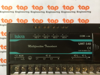
Instrument Description Multifunction Transducer Network Recorder Network Analyzer
ANSI type UMT 540 UMT 550 UMT 560
DIN type MT 540 MT 550 MT 560
Hardware Configuration
Accuracy class (typical, of reading) % 0.2 0.2 0.2
Power supply Uni-LO / Uni-HI* Uni-LO / Uni-HI* Uni-LO / Uni-HI*
Energy counters 4 4 4
Real time clock • • •
Remote display connection*** • • •
FLASH Memory size - 8 Mb 8 Mb
Autorange Current • • •
Autorange Voltage • • •
Input Range
Current - In=5 A, max.12 A • • •
Voltage - Un=500 V L-N, max. 750 V L-N sin • • •
Frequency - 16 2/3 Hz or 45 to 65 Hz or 300 Hz or 400 Hz • • •
Communication
Communication ports 1 Standard + 1 Optional *** 1 Standard + 1 Optional *** 1 Standard + 1 Optional ***
Comm. type: Serial (RS485 + RS232)/Ethernet/USB/Ethernet & USB** • / • / - / • • / • / - / • • / • / - / •
Comm. protocol: Modbus (RTU, TCP) and DNP3 • • •
Inputs/Outputs
I/O 1: AN / DI / DO / PO / TI / AL / / / / / / / / / / / / / / /
I/O 2: AN / DI / DO / PO / TI / AL / / / / / / / / / / / / / / /
I/O 3: AN / DI / DO / PO / TI / AL / / / / / / / / / / / / / / /
I/O 4: AN / DI / DO / PO / TI / AL / COM2* / / / / / / / / / / / / / / / / / /
Available Functions
Programmable refresh time (Communication) • • •
MD calculation (TF, FW, SW) • • •
Tariff clock • • •
Cost management • • •
Programmable alarms 32 32 32
Alarms recording - • •
Measurements recording - • •
Power supply quality EN50160 - - •
PC Software MiQen MiQen MiQen
Available Measurements
Actual values: U, I, P, Q, S, PF, PA, f, ϕ • • •
Energy • • •
Maximum demands • • •
Minimum values: U, I, P, Q, S, PF, PA, f, ϕ • • •
Maximum values: U, I, P, Q, S, PF, PA, f, ϕ • • •
THD • • •
Harmonics up to 31st up to 31st up to 63rd
AN - analogue output
DI - digital input
DO - digital output
TF - thermal function
FW - fixed window
SW - sliding window
/ - or
MT 5x0/UMT 5x0
- Comparison and common characteristics
Measuring Transducers
17
The transducer measures and records the following characteristics:
• Frequency deviations
• Voltage deviations
• Voltage clips
• Voltage interruptions
• Voltage unbalances
• Over-voltages
• Fast voltage changes
• Flicker intensity
• THD
• Harmonics
Besides the features listed in the chapter “Family of Measuring Transducers MT 5x0/UMT 5x0 - comparison and
common characteristics”, the transducer also has other features:
• Harmonic analysis of phase, phase-to-phase voltages and currents up to the 63rd harmonic (only MT/UMT 560)
• 32 adjustable alarms
• Recording up to 32 measurands and 32 alarms in the internal memory (8 MB flash)
Dimensional drawings on page 81.
Connection diagrams on pages 94-97.
Software on pages 32-35.
MT 560/UMT 560 - TRANSDUCER & ANALYZER
USE
The MT 560/UMT 560 multi transducer and
analyzer is used for a permanent analysis of
electricity supply quality in compliance with the
EN 50160 standard. Records are stored in the
internal memory for the period of the last three
years. Moreover, more than 100,000 deviations
of the measurands from the standard values are
stored, which enables finding eventual reasons for
the problems in network.
Input ranges width enables measurement of all
basic AC voltages and currents. The transducer
generates and accepts different I/O signals.
An analogue output signal is proportional to measurand
and is intended for the control of analogue
and digital devices. A pulse output is intended for
sending data to devices for checking and supervising
consumed energy.
Measuring Transducers
18
USE
The MT 550/UMT 550 transducer and analyzer is used for monitoring, measuring and recording measurements of
electric quantities in electrical power distribution system. Measurements are stored in internal flash memory (8 MB).
Both measuring transducers (U)MT 550 and (U)MT 540 measure basic parameters (U, I, P) very precisely with
accuracy class 0.2 according to the IEC EN 60688 standard.
Input range width enables measurement of all basic AC voltage or current. The transducer generates and
accepts different I/O signals. An analogue output signal is proportional to measurand and is intended for the
control of analogue and digital devices. A pulse output is intended for sending data to devices for checking and
supervising consumed energy.
Besides the features listed in the chapter “Family of Measuring Transducers MT 5x0/UMT 5x0 - comparison and
common characteristics”, the transducer also has other features:
• Harmonic analysis of phase, phase-to-phase voltages and currents up to the 31rd harmonic
• 32 adjustable alarms
• Recording up to 32 measurands and 32 alarms in the internal memory (8 MB flash, only MT/UMT 550).
Dimensional drawings on page 81.
Connection diagrams on pages 94-97.
Software on pages 32-35.
MT 550/UMT 550 - TRANSDUCER & RECORDER,
MT 540/UMT 540 - MULTIFUNCTION TRANSDUCER
Measuring Transducers
19
USB 2.0
RS232/485
RS485
1 2 32
MODBUS TCP
ETHERNET
Features:
• Remote application for measuring transducers
(U)MT560, (U)MT550, (U)MT540
• Network connection for up to 32 transducers
• RS485 communication
• Universal power supply 48-276 V AC, 20-300 V DC
• Graphical LCD 128 x 64 dots
• Multilingual support
Remote display is very useful for a quick survey of all
measured parameters or for setting up the (U)MT5xx
measuring transducers without the PC. Navigation keys
and graphical LCD display enable remote application
and remote display settings. By choosing different RD
500 target communication addresses it is possible to
track measurements and change settings for up to 32
(U)MT 5x0 measuring transducers.
RD 500 - REMOTE DISPLAY FOR MEASURING
TRANSDUCERS MT 5x0/UMT 5x0
Dimensional drawings on page 81.
Measuring Transducers
20
MT 510/UMT 510 - POWER TRANSDUCER
(U)MT 510 is intended for measuring and monitoring single-phase electrical power network. Voltage and current inputs
are electrically isolated from the system by means of highly resistive input chain and current transformer respectively.
It measures true RMS values by means of fast sampling of voltage and current signals, which makes instruments suitable
for acquisition of transient events. A built-in microcontroller calculates measurands (voltage, current, frequency,
energy, power, power factor, power angles, THD U, THD I, MD) from the measured signals.
Features
• Measurements of instantaneous values of all single phase values; U, I, P, Q, S, f, ϕ, energy, THD U, THD I, MD
• Power accuracy class 0.2
• 16 adjustable alarms
• Wide frequency range from 16 Hz to 400 Hz
• RS 232/RS 485 communication up to 115,200 bit/s or USB communication or Ethernet and USB
communication simultaneously
• MODBUS communication protocol
• Up to 2 inputs or outputs (analogue outputs, digital inputs, alarm (digital) outputs, pulse outputs)
• Universal power supply (two voltage ranges)
• Automatic range of nominal current and voltage (max. 12.5 A and 600 VL-N)
• Housing for a DIN rail mounting
• User-friendly PC MiQen software
Dimensional drawings on page 81.
Connection diagrams on pages 98.
Software on pages 32-35.
Measuring Transducers
21
MT 511/UMT 511 - POWER TRANSDUCER & RECORDER
(U)MT 511 is intended for measuring and monitoring single-phase electrical power network. Voltage and current inputs
are electrically isolated from the system by means of highly resistive input chain and current transformer, respectively.
It measures true RMS values by means of fast sampling of voltage and current signals, which makes instruments suitable
for acquisition of transient events. A built-in microcontroller calculates measurands (voltage, current, frequency,
energy, power, power factor, power angles, THD U, THD I, MD) from the measured signals.
Features
• Measurements of instantaneous values of all single phase values; U, I, P, Q, S, f, ϕ, energy, THD U, THD I, MD
• Power accuracy class 0.2
• Recording of up to 8 measurands and 16 alarms in the internal memory (8 MB flash)
• 16 adjustable alarms
• Wide frequency range from 16 Hz to 400 Hz
• RS 232/RS 485 communication up to 115,200 bit/s or USB communication or Ethernet and USB
communication simultaneously
• MODBUS communication protocol
• Up to 2 inputs or outputs (analogue outputs, digital inputs, alarm (digital) outputs, pulse outputs)
• Universal power supply (two voltage ranges)
• Automatic range of nominal current and voltage (max. 12.5 A and 600 VL-N)
• Housing for a DIN rail mounting
• User-friendly PC MiQen software
Dimensional drawings on page 81.
Connection diagrams on pages 98.
Software on pages 32-35.
Measuring Transducers
22
(U)MT 516 is intended for measuring and monitoring single-phase electrical power network. Voltage input is electrically
isolated from the system by means of highly resistive input chain. It measures true RMS voltage value by means of
fast sampling of voltage signals, which makes instruments suitable for acquisition of transient events. A built-in microcontroller
calculates measurands (voltage, frequency, THD U) from the measured signals. Measurands can then be
converted into load independent DC current or voltage which is proportional to the true RMS measured value for the
purpose of regulating analogue and/or digital devices.
Features
• Measurements of true RMS voltage, frequency THD U
• High accuracy class 0.2 (IEC-688)
• Wide frequency range from 16 Hz to 400 Hz
• 16 adjustable alarms
• RS 232/RS 485 communication up to 115,200 bit/s or USB communication or Ethernet and USB
communication simultaneously
• MODBUS communication protocol
• Up to 2 inputs or outputs (analogue outputs, digital inputs, alarm outputs, digital outputs)
• Universal power supply (two voltage ranges)
• Automatic range of nominal voltage (max. 600 VL-N)
• Housing for a DIN rail mounting
• User-friendly PC MiQen software
Dimensional drawings on page 81.
Connection diagrams on pages 98.
Software on pages 32-35.
MT 516/UMT 516 - VOLTAGE TRANSDUCER
Measuring Transducers
23
(U)MT 518 is intended for measuring and monitoring single-phase electrical power network. Input current is electrically
isolated from the system by means of current transformer. (U)MT518 measures true RMS current value by means of
fast sampling of current signals, which makes instruments suitable for acquisition of transient events. A built-in microcontroller
calculates measurands (current, frequency, THD I) from the measured signals. Measurands can then be
converted into load independent DC current or voltage which is proportional to the true RMS measured value for the
purpose of regulating analogue and/or digital devices.
Features
• Measurements of true RMS current, frequency, THD I
• High accuracy class 0.2 (IEC-688)
• Wide frequency range from 16 Hz to 400 Hz
• 16 adjustable alarms
• RS 232/RS 485 communication up to 115,200 bit/s or USB communication or Ethernet and USB
communication simultaneously
• MODBUS communication protocol
• Up to 2 inputs or outputs (analogue outputs, digital inputs, alarm outputs, digital outputs)
• Universal power supply (two voltage ranges)
• Automatic range of nominal current (max. 12.5 A)
• Housing for a DIN rail mounting
• User-friendly PC MiQen software
Dimensional drawings on page 81.
Connection diagrams on pages 98.
Software on pages 32-35.
MT 518/UMT 518 - CURRENT TRANSDUCER
Measuring Transducers
24
MT406 is intended for measuring and monitoring voltage in electrical power network. Voltage input is electrically
insulated from the system by means of voltage transformer. The signal is rectified, smoothed and amplified into an
independent DC current output.
APPLICATION
The MT406 voltage transducer is used for a permanent monitoring of a single-phase voltage value. PLCs, PCs, microprocessor
control, indicators, alarms units etc. can be operated by the output signal. Voltage input can be connected
either directly to low-voltage network or shall be connected to network via a corresponding voltage transformer (with
standard 100V output).
Features:
• Sinusoidal AC voltage measurements
• Voltage range measurements up to 500 VL-N
• Galvanic insulation between input and output
• Accuracy class 0.5
• Self powered
• Housing for DIN rail mounting
Dimensional drawings on page 81.
Connection diagrams on pages 99.
MT 406 - AC VOLTAGE SELF POWERED TRANSDUCER
Measuring Transducers
25
MT 408 - AC CURRENT SELF POWERED TRANSDUCER
MT408 is intended for measuring and monitoring single-phase electrical power network. Current input is electrically
insulated from the system by means of current transformer. The signal is rectified, smoothed and amplified into an
independent DC current output.
APPLICATION
The MT408 current transducer is used for a permanent monitoring of a single-phase current value. PLCs, PCs, microprocessor
control, indicators, alarms units etc. can be operated by the output signal. Current input can be connected
either directly to low-voltage network or shall be connected to network via a corresponding current transformer (with
standard 1 A or 5 A output).
Features:
• Sinusoidal AC current measurements
• Current range measurements up to 6 A
• Galvanic insulation between input and output
• Accuracy class 0.5
• Self powered
• Housing for DIN rail mounting
Dimensional drawings on page 81.
Connection diagrams on pages 99.
Measuring Transducers
26
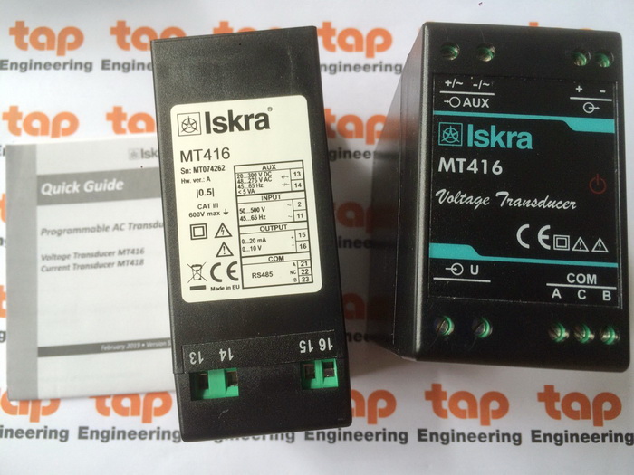
MT 416 - PROGRAMMABLE AC VOLTAGE TRANSDUCER
APPLICATION
The MT416 voltage transducer is used for a permanent monitoring of a single-phase voltage and frequency values.
MT416 is delivered configured to default values. Subsequent customer configuration is possible with user friendly
setting software MiQen. MT416 supports standard serial RS232/485 with speed up to 115200 bps. USB 2.0 can be
used for a fast set-up or memory acquisition (after installation USB connection is not possible any more). Additional
USB 2.0 interface can only be used for a fast set- up without need for auxiliary power supply. This interface is NOT
galvanically isolated from analogue output and can be used ONLY unconnected to aux. supply and measuring
inputs.
Features:
• True RMS AC voltage measurements
• Voltage auto range measurements up to 600 VL-N
• Frequency measurement range 16 - 400 Hz
• AC or universal wide auxiliary power supply range 24 - 300 Vdc, 40 - 276 Vac
• Accuracy class 0.5 (EN 60688)
• Serial (RS232 or RS485) communication
• Sophisticated analogue output; 2 voltage and 4 current ranges, non-linear characteristics …
• Simple USB setting without auxiliary power supply
PROPERTIES
• Measurements of true RMS voltage, frequency THD U and MD
• Accuracy class 0.5 (EN 60688)
• Input frequency range: 50/60 Hz, 400 Hz
• RS 232/RS 485 communication up to 115, 200 bit/s and USB 2.0 communication
• MODBUS communication protocol
• Universal power supply or transformer power supply
• Automatic range (max. 600 VL-N)
• Housing for DIN rail mounting
• User-friendly PC MiQen software
MT416 is intended for measuring and monitoring
single-phase electrical power network. Voltage
input is electrically isolated from the system by
means of voltage transformer. It measures true
RMS voltage value by means of fast sampling of
voltage signals, which makes instruments suitable
for acquisition of transient events. A built-in
microcontroller calculates measurands (voltage,
frequency, THD U, MD) from the measured signals.
Measurands (U, f) can be then converted
into load independent DC current or voltage
which is proportional to the true RMS measured
value for the purpose of regulation of analogue
and/or digital devices.
Dimensional drawings on page 81.
Connection diagrams on pages 99.
Software on pages 32-35.
Measuring Transducers
27
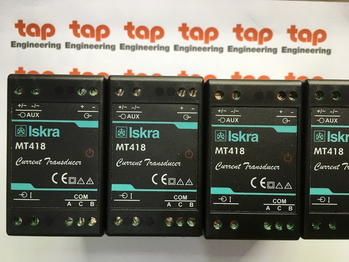
MT 418 - PROGRAMMABLE AC CURRENT TRANSDUCER
APPLICATION
The MT418 current transducer is used for a permanent monitoring of a single-phase current and frequency values.
MT418 is delivered configured to default values. Subsequent customer configuration is possible with user friendly setting
software MiQen. MT418 supports standard serial RS232/485 with speed up to 115200 bps. USB 2.0 can be used
for a fast set-up or memory acquisition (after installation USB connection is not possible any more). Additional USB 2.0
interface can only be used for a fast set- up without need for auxiliary power supply. This interface is NOT galvanically
isolated from analogue output and can be used ONLY unconnected to aux. supply and measuring inputs.
Features:
• True RMS AC current measurements
• Current auto range measurements up to 12 A
• Frequency measurement range 16 - 400 Hz
• AC or universal wide auxiliary power supply range 24 - 300 Vdc, 40 - 276 Vac
• Accuracy class 0.5 (EN 60688)
• Serial (RS232 or RS485) communication
• Sophisticated analogue output; 2 voltage and 4 current ranges, non-linear characteristics …
• Simple USB setting without auxiliary power supply
PROPERTIES
• Measurements of true RMS current, frequency, THD I and MD
• Accuracy class 0.5 (EN 60688)
• Input frequency range: 50/60 Hz, 400 Hz
• RS 232/RS 485 communication up to 115,200 bit/s and USB 2.0 communication
• MODBUS communication protocol
• Universal power supply or transformer power supply
• Automatic range (max. 12 A)
• Housing for DIN rail mounting
• User-friendly PC MiQen software
MT418 is intended for measuring and monitoring
single-phase electrical power network. Current input
is electrically isolated from the system by means of
current transformer. It measures true RMS current
value by means of fast sampling of current signals,
which makes instruments suitable for acquisition of
transient events. A built-in microcontroller calculates
measurands (current, frequency, THD U, MD) from
the measured signals. Measurands (I, f) can be then
converted into load independent DC current or voltage
which is proportional to the true RMS measured
value for the purpose of regulation of analogue and/
or digital devices.
Dimensional drawings on page 81.
Connection diagrams on pages 99.
Software on pages 32-35.
Measuring Transducers
28
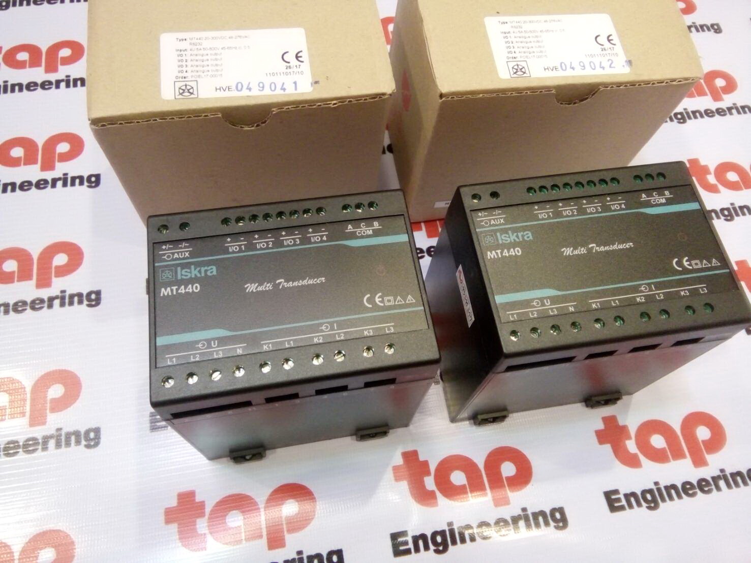
MT 440 - MULTIFUNCTIONAL TRANSDUCER
APPLICATION
The MT440 multifunction transducer is used for measuring and monitoring of all single-phase or three-phase values.
Wide range of various I/O modules makes MT440 a perfect choice for numerous applications. MT440 is delivered
un-configured for customer configuration with user friendly setting software MiQen. MT440 supports standard serial
communication RS232 or RS485 with speed up to 115200 baud, which is perfect for simple applications and serial
bus interfacing. Additional USB 2.0 interface can only be used for a fast set-up without need for auxiliary power supply.
This interface is NOT galvanically isolated from power inputs (aux. supply and measurement inputs) and can be
used ONLY unconnected to power inputs.
Features:
• Voltage and current auto range measurements up to 600V, 12.5A
• Universal wide auxiliary power supply range 24 - 300 Vdc, 40 - 276 Vac
• Power accuracy class 0.5 (EN 60 688)
• Up to four I/O modules (analogue out, pulse out, alarm out, general purpose digital out)
• Sophisticated analogue out; 2 voltage and 4 current ranges, non-linear characteristics …
• Simple USB setting without auxiliary power supply
PROPERTIES
• Measurements of instantaneous values of more than 50 quantities
(V, A, kW, kVA, kvar, kWh, kvarh, PF, Hz, MD thermal, THD, etc)
• Power accuracy class 0.5
• 16 adjustable alarms
• Input frequency: 50/60 Hz, 400 Hz
• Serial communication (RS232 or RS485 up to 115,200 bit/s) and USB 2.0
• MODBUS communication protocol
• Up to 4 I/O (analogue outputs, alarm outputs, pulse outputs, general purpose relay output,
general purpose solid-state output)
• Single wide auxiliary power supply range 24 - 300 Vdc, 40 - 276 Vac
• Automatic range of current and voltage (max. 12.5 A and 600 VL-N)
• Housing for DIN rail mounting
• User-friendly setting software, MiQen
MT440 are intended for measuring and monitoring
single-phase or three-phase electrical power
network. They measure RMS value by means of
fast sampling of voltage and current signals, which
makes instruments suitable for acquisition of transient
events. A built-in microcontroller calculates
measurands (voltage, current, frequency, energy,
power, power factor, THD phase angles, etc.) from
the measured signals.
Dimensional drawings on page 81.
Connection diagrams on pages 100.
Software on pages 32-35.
Measuring Transducers
29
MI 4xx - MEASURING TRANSDUCER
• Resistance MI 452
• DC voltage MI 456
• DC current MI 458
• Temperature with Pt 100 MI 450
• TAP position MI 454
Type / Description Accuracy class Inputs Housing width (a)
MI 452 Temperature with Pt 100, Pt 1000, Ni 100 0.5 2-wire, 3-wire, 4-wire 45 mm
MI 452 Resistance
0.5
R = 0 … 10 Ω … 50 kΩ
R = 0 … 100 Ω … 500 kΩ
45 mm
MI 454 TAP position
0.5
100 Ω … 50 kΩ
1000 Ω … 500 kΩ
45 mm
MI 456 DC voltage
0.5
U = 50 mV … 1 V DC
U = 1 V … 50 V DC
U = 50 V … 400 V DC
45 mm
MI 458 DC current
0.5
I = 1 … 10 mA DC
I = 10 … 100 mA DC
45 mm
AC auxiliary power supply: 57, 63.5, 100, 110, 230, 400, 500 V
Options:
RS 232 or RS 485 serial communication port
Universal aux. power supply for DC & AC 24 … 300 V DC / 40 … 276 V AC
* Power supply from a measuring circuit only. Communication port and aux. power supply are not available. Output 0.5 mA, 10 mA, 20 mA.
Dimensional drawings on page 81.
Connection diagrams on pages 101.
Software on pages 32-35.
30
Communicators
PLUG AND PLAY “OUT-OF-THE-BOX” DEVICE
FOR MONITORING/RECORDING/CONVERTING/
ALERTING DATA
USE
• For buildings managers and owners, utility
companies, AMR solutions, EM solutions
providers.
• PCCI (Point-of-Common-Coupling Interface) for
integration of Smart Grids and Distributed d Energy
Resources. PCCI is used for a simple, standardized
connection of micro and small generation of
electricity from distributed resources to the distribution
network. PCCI functionalities include remote
monitoring and control, communication with the
control center, power quality monitoring according
to EN 50160, possibility of controlling compensation
devices, various protection functions (voltage,
frequency, island operation, etc.).
• Concentrator/Converter - used as protocol
converter between Iskra-MIS products and other
devices. IEC61850 module in server configuration
already supported, DNP3 slave module in a development
stage.
• LiSa - MiBox is a basic module of a LiSa system.
LiSa is a system for detection of different errors on
middle-voltage overhead transmission lines and
transformer stations.
FEATURES:
• Embedded platform with middle range requirements
• Preinstalled MiSmart application
• The unit is independent from external resources with all the system’s components already included (measuring
system, database, set-up application and monitoring application)
• For monitoring/collecting data from measuring devices, alert handling, controlling and data management
• administration of the MiBox and data analysis/management is supported also over a web interface
• IP-based network (Ethernet, GPRS/UMTS, optionally WiFi) for primary use and with local communication (USB,
serial) for secondary use
• Function of protocol conversion
• Industrial temperature range from -25°c to +50°c
BENEFITS:
• Extensions of the existing systems and applications possible
• Upgrade possibilities (local and remote)
• Cost benefits due to the partial upgrades
• Open platform with customer add-on extensions
• Support for standard communication protocols (IEC61850, OPC, ...)
MiBox
Dimensional drawings on page 81.
Connection diagrams on pages 90, 91.
Software on pages 31-34.
Measuring Centres
31
MiBOX
32
Software
MIQEN
MiQen software is a tool for complete monitoring of the measuring instruments. RS485/RS232 or TCP/IP communication
is used for connection with a PC. A user-friendly interface consists of five segments: device management, counter
settings, real-time measurements, data analyses and programs updating.
Device managament
As easy as possible.
Just select the device in a favourites line.
Use the network explorer to set and explore the
devices network. Communication parameters of
all devices and their addresses in network can be
easily set.
Instrument setting
Multi Register Edit technology assures a simple
modification of settings that are organised in tree
structures. Besides settings transfer into the
instrument, storing and reading from the setting files
and MMCs are also available.
Real-time measurement
All supported measurements can be seen in real time
in a table form, while harmonics and their time-reconstructed
signals are also displayed graphically. For further
processing of the results of measurements, copying
via a clipboard into standard Windows
formats is supported.
33
Software
MIQEN
Data analysis
Analysis can be performed for the instruments with a
built-in memory. Recorded quantities can be monitored
in a tabular or graphical form, events that triggered
alarms can be analysed or a report on quality of supply
voltage can be made. All data can be exported to the
Access data base, Excel worksheets or text files.
Programs updating
Always use the latest version of software, both MiQen
and software in the instrument. The program automatically
informs you on available upgrades that can be
transferred from the web site and used for upgrading.
System requirements:
Windows 98, 2000, Millennium, XP, NT4.0, 100 MB capacity on a hard disc, VGA Screen, 64 MB RAM, CD drive,
RS232 communication port
There are two versions of MIQEN software:
• standard edition - all functions available except for data analysis, free of charge
• professional edition - all functions available for installation, you have to buy a CD key
34
MiSMART
MiSMART
MiSMART is an integrated software platform for centralized acquisition, storage and representation of data captured
by distributed measurement devices. It enables monitoring of a large number of metering points. All captured data
can be remotely accessed by a simple web browser. Easy integration of third party tools and data analysis software
make it highly adaptable to any range of customized user applications. The most common fields of implementation
are energy management, monitoring of energy production, transformer station monitoring, automated meter reading
etc.
Customer benefits
• complete turn-key solution for remote data acquisition and management
• integrated tools for data management
• highly customized for Iskra MIS measurement devices for efficient system operation
• utilization of wide range of communication technologies for best network configuration (serial, ethernet, GPRS, SMS,
low power radio etc.)
• immediate alarming and notification
• reliable off-load data collection, based on data redundancy
• easy integration of third party tools and software
MiSMART PLAtform:
• MiSMART data collector
• MiSMART database
• MiSMART web server
Windows based platform with three-tier architecture for efficient platform management.
It utilizes innovative push data collection mechanism combined with advanced instrumets with built in memory for data
redundancy resulting in high data collection reliability.
MiSMART DATA COLLECTOR:
• captures measurements, alarms, settings and power quality reports
• real time alarm management
• automatic time synchronization of devices
• possible compressed binary data transfer to minimize network load
• configurable data resolution
MiSMART DATABASE:
• stores measurements, alarms, settings and power quality reports
• implemented on MSSQL database
• centralized or distributed data storage
• standard database interfaces enable easy access to external third party applications
MiSMART WEB SERVER:
• multi client connections
• multi user management
• graphical and numerical data representation
• web configuration and activity monitor
• monitoring of measurements, alarms and power quality reports
A user client can connect to the MiSMART Web Server with a standard internet browser.
35
MiSMART
MiSMART
MiSMART
Database
MiSMART
Web
Server
MiSMART
data collector
MiSMART
Clients
MiSMART
PLATFORM
LAN
INTERNET
VPN
Communication Adapters
36
MI 480 is a device with a built-in GPRS modem interface for collecting and sending measurements from the connected
instruments to the web portal. It is ideal for controlling distant objects, such as power plants, pumps, transformer stations,
measuring stations, temperature monitoring…).
Data are collected in the MI 480 internal memory and sent in packets via the GPRS communication to the web portal.
Alarms can be immediately forwarded to various mobile phone numbers.
Main features are:
• Alarms via an SMS message to a mobile phone
• Trend alarms via an SMS message to a mobile phone
• Data on instantaneous measurements via SMS
• Sending measurement packages to the server for further processing
• Survey of all measurements via a web portal
• All settings are accessible via a web portal
Due to its characteristics, MI 480 is an ideal instrument to be used in systems where permanent or periodical
monitoring, storing the measurements for momentary and later analysis and processing are required. The system can
be adapted to the needs and requirements of the individual user or system to which it is built-in.
Dimensional drawings on page 81.
Connection diagrams on pages 101.
MI 480 - GSM DEVICE FOR REMOTE CONTROL
Communication Adapters
37
RS485
RS485
RS485 communication
RS485 communication enables connection of up to 32 instruments with one MI 480 device. It is limited to the
maximum connection length of 1000 m. Connection of the RS485 communication is described in tables and figures
below.
Contacts for RS485 communication
MI 480 RS485 Measuring centres Measuring transducers
A (21) DATA + A (8) A (21)
B (23) DATA - B (7) B (23)
MI 480 MI 485 RS485 MI 485 RS232 Measuring centres Measuring transducers
A (21) A (21) Rx (24) Rx (3) Rx (24)
GND (25) GND (5) GND (25)
B (23) B (23) Tx (26) Tx (2) Tx (26)
Contacts for connection via MI485 interface
Web portal
The web portal is the user's access point for setting and analysing collected data. It is used in a remote control system
for a small power station and a system for detecting cut transmission lines and controlling transformer station defects.
For better understanding of information flow see the figure below.
Connection of the instrument via MI 485 interface
MI 480 - GSM DEVICE FOR REMOTE CONTROL
Connection of modem interface
RS485
Communication Adapters
38
MI 485 can be used for integrating devices with RS232
communication into RS485 network or as a connection
between RS485 network and a control device (PC, PLC,
etc.)
The MI 485 communication adapter is used for converting
RS485 signal to RS232 signal and vice versa. Signals
are electrically isolated. No settings are required and the
device is ready for use. Communication speed is up to
115,200 bps.
Connections:
• Auxiliary supply - connected with connection terminals 13, 14
• RS 232 communication, max. length 3 m
• RS 485 communication, up to 32 devices, a line should be terminated with a 120 Ω resistor.
Dimensional drawings on page 81.
Connection diagrams on pages 101.
MI 485 - RS232/RS485 INTERFACE
MI 485 Computer - DB9
Tx (26) Rx (2)
Rx (24) Tx (3)
GND (25) GND (5)
MI 485 RS 485-instruments
A (21) DATA +
B (23) DATA -
Communication Adapters
39
The MI 486, MI 488 communication adapters are
used for connecting the instruments with RS232 or
RS485
communication on the Ethernet network. The instruments
are connected to the computer through the
Ethernet network. Signals are electrically isolated.
Data are read from the instruments through interfaces.
Communication speed is up to 115,200 bps.
MI 486 Computer - DB9
Tx (26) Tx (2)
Rx (24) Rx (3)
GND (25) GND (5)
Connections:
• Auxiliary supply - connected with connection terminals 13, 14
• Ethernet connection - connected with 10/100 RJ45 connection terminal
• RS232 communication (for MI 486), max. length 3 m
MI 488 Instruments with RS485
A (21) DATA +
B (23) DATA -
• RS485 communication (for MI 488), up to 32 devices, a line should be terminated with a 120 Ω resistor.
Dimensional drawings on page 81. Connection diagrams on pages 101.
MI 486 − RS232 INTERFACE - TCP/IP
MI 488 − RS485 INTERFACE - TCP/IP
Digital Meters
40
DIGITAL METERS WITH LED DISPLAY
Digital meters with LED display enable fast and
accurate survey of electric quantities and are
convenient for industrial use as well as for the
production and distribution of electric energy.
They are panel mounted and enable measurement
of TRMS values of electric quantities.
Features:
• True RMS measurements
• LED Displays with 4 or 3 digits
• Measurement ranges from 0...500 V and 0...9999 A
• CT ratio adjustment for A-meters ... /5 A
• CT ratio from 1 … 2000
• Measurement range for Frequency meters 20 … 500 Hz.
• Accuracy ± 1 % (± 0.2 % for Frequency meters)
• Power supply 230 V AC ± 20 %, 50/60 Hz
• Power consumption < 3 VA
• Ambient temperature: - 5 °C ... + 55 °C
Digital Meters
41
Type
DM 206
Voltmeter
DM 208
Ammeter
DM 306
Voltmeter
DM 308
Ammeter
DM 310
Multimeter
DM 202
Frequency
meter
DM 302
Frequency
meter
Front frame (mm) 72 x 72 72 x 72 96 x 96 96 x 96 96 x 96 72 x 72 96 x 96
Display 3-digit 4-digit 3-digit 4-digit
Ammeter: 3 x 4-digit
Voltmeter: 3-digit
Frequency meter: 3-digit
3-digit 3-digit
Accuracy ± 1 % + 2d ± 1 % + 2d ± 1 % + 2d ± 1 % + 2d
Ammeter: ± 1 % + 2d
Voltmeter: ± 1 % + 2d
Frequency meter:
± 0,2 % + 2d
± 0,2% + 2d ± 0,2% + 2d
Measuring range 0…500 V 0…9999 A 0…500 V 0…9999 A
Ammeter: 0…9999 A
Voltmeter L1, L2, L3:
0…500 V
Frequency meter:
30…70 Hz
20…500 Hz
(30…500 V AC)
20…500 Hz
(30…500 V AC)
Power Supply 230 V AC ± 20%, 50/60 Hz
CT ratio* - 1…2000 - 1…2000 1…2000 - -
Power consumption < 3 VA < 3 VA < 3 VA < 3 VA <= 3 W <= 3 W <= 3 W
Ambient
temperature
- 5 °C … + 55 °C
Weight (kg) 0,23 0,23 0,28 0,28 0,29 0,26 0,30
*CT ratio: 1, 2, 3, 4, 5, 6, 8, 10, 12, 15, 20, 25, 30, 40, 50, 60, 80, 100, 120, 150, 160, 200, 250, 300, 320, 360, 400, 500, 600, 700, 800, 900,
100, 1200, 1400, 1600, 1800, 2000.
Dimensional drawings on page 83.
DIGITAL METERS WITH LED DISPLAY
Synchronization Meters
42
SQ 0214
ZQ 1207
FQ 1207
SQ 0104, SQ 0114, SQ 0204, SQ 0214,
ZQ 1207, FQ 1207, ZQ 1208, FQ 1208
If you want to synchronise a generator and a bus bar
manually or semi-automatically, SQ 0214 and SQ 0204
are the right instruments for you. Our synchronization
meters are very unique products, especially SQ 0214.
Synchronization meters are intended for manual or semiautomatic
synchronization of two electric-energy
distribution systems. SQ 0204, SQ 0214 synchroscopes
are the instruments for measuring a phase angle
between two electric-energy distribution systems. The
SQ 0214 type also measures voltages and frequencies
of both systems. On request, both types can be
on request provided with a built-in relay output which
signalises if the conditions for synchronization have been
met. ZQ 1207 or ZQ 1208 two-system frequency meter
is used for measuring frequencies in two networks. FQ
1207 or FQ 1208 double voltage meter measures voltages
in two networks.
* ZQ 1208 and FQ 1208 for front frame 144 x 144 mm on request.
** Other ratings on demand
Ship version meters SQ 0204, SQ 0214, ZQ 1207 and FQ 1207 are available on request.
Two voltages (Ugen, Ubb) and two frequencies (fgen, fbb) are displayed on LCD at SQ 0214.
When the difference between fgen and fbb is smaller than 0.02 Hz, UBUS, UGEN, FBUS and Δϕ are displayed.
Bus-bar voltage Ubb Bus-bar frequency fbb
Generator voltage Ugen Generator frequency fgen
Bus-bar voltage Ubb Phase difference Δϕ
Generator voltage Ugen Bus-bar frequency fbb
TYPE SQ 0104 SQ 0114 SQ 0204 SQ 0214 ZQ 1207 ZQ 1108 ZQ 1208 FQ 1207 FQ 1108 FQ 1208
Front frame (mm) 144 x 144 144 x 144 96 x 96 96 x 96 96 x 96 144 x 144 96 x 96* 96 x 96 144 x 144 96 x 96*
Cutting for mounting (mm) 138 x 138 138 x 138 92 x 92 92 x 92 92 x 92 138 x 138 92 x 92 92 x 92 138 x 138 92 x 92
Scale length (mm) 360˚ 360˚ 360˚ 360˚ 92/72 2 x 50 2 x 50 92/72 2 x 50 2 x 50
Accuracy class +/-1˚ el. +/-1˚ el. +/-1˚ el. +/-1˚ el. 0.5 0.5 0.5 1.5 1.5 1.5
RATING
100 V, 230 V • • • • • • • • • •
400 V • • • • • • • • • •
500 V •** •** •** •** • • •
600 V •** •** •** •** • •
Frequency • • • • •
Dimensional drawings on page 73.
Connection diagrams on pages 103.
Energy Meters with Power Display
43
WQ 1217
WQ 0217, WQ 1217, WQ 0207, WQ 2207, WQ 1247
WQ 2207
Dimensional drawings on pages 77-79.
Connection diagrams on pages 93.
Energy meters display instantaneous power in single and
three-phase systems with balanced or unbalanced load.
Accuracy classes are 1 for energy measurement (EN
61036), 1.5 for power measurement and 2.5 power factor
measurement.
TYPE WQ 0217 WQ 1217 WQ 0207 WQ 2207 WQ 1247
Front frame (mm) 96 x 96 96 x 96 96 x 96 96 x 96 96 x 96
Cutting for mounting (mm) 92 x 92 92 x 92 92 x 92 92 x 92 92 x 92
Scale length (mm) / Number of counters - / 1 - / 2 95 / 1 125 / 1 - / 2 LCD
Voltage input 100 V, 110 V, 230 V, 400 V, 500 V
Current input 1 A, 5 A
1b,1br Single phase system • • • • •
3b, 3br Three-phase three-wire balanced load system • • • • •
3u, 3ur Three-phase three-wire balanced load system • • • • •
4b, 4br Three-phase four-wire balanced load system • • •
4u, 4ur Three-phase four-wire unbalanced load system • • • • •
Option
One impulse output • • • • •
Two impulse outputs • • • • •
57 V, 110 V , 230 V, 400 VAC
Auxiliary supply • • • • •
Hour Meters & Pulse Counters
44
HK 46 HK 47 HK 48, HK 49 HK 30
HK 46 HK 47 HK 48, HK 49 HK 30
Voltages
AC
24 V, 48 V, 60 V, 110 V, 120 V, 230 V,
240 V, 400 V (±10%)
24 V, 48 V, 60 V, 110 V, 120 V, 230 V,
240 V, 400 V (±10%)
24 V, 48 V, 60 V, 110 V, 120 V, 230 V,
240 V, 400 V (±10%)
24 V, 48 V, 60 V, 110 V, 120 V, 230 V, 240
V, 400 V (±10%)
Frequency 50 Hz, 60 Hz 50 Hz, 60 Hz 50 Hz, 60 Hz 50 Hz, 60 Hz
Counting range 99999.99 h 99999.99 h 99999.99 h 99999.99 h
Number of digits 5 integers, 2 decimals 5 integers, 2 decimals 5 integers, 2 decimals 5 integers, 2 decimals
Operating temperature -25 °C … +80 °C -25 °C … +80 °C -25 °C … +80 °C -25 °C … +70 °C
Voltages
DC
6-30 V, 10-80 V, 110 V
(±10%)
6-30 V, 10-80 V, 110V
(±10%)
6-30 V, 10-80 V, 110 V
(±10%)
6-12 V, 12-36 V, 36-80 V, 110 V
(±10%)
Counting range 999999.9 h 999999.9 h 999999.9 h 999999.9 h
Number of digits 6 integers, 1 decimal 6 integers, 1 decimal 6 integers, 1 decimal 6 integers, 1 decimal
Operating temperature -20 °C … +70 °C -20 °C … +70 °C -20 °C … +70 °C -10 °C … +55 °C
HK 46 HK 47 HK 48, HK 49 HK 30
Protection IP40, front side IP65, front side IP40, front side IP40, front side
IP20, terminals IP00, terminals IP00, terminals IP20, terminals
Front dimensions 48 x 48 mm Ø 58 mm HK 48 72 x 72 mm - HK 49 96 x 96 mm 36 x 24 mm
Adapter frames 52x52, 55x55, 72x72, Ø 80 mm Ø 72 mm, Ø 80 mm
48 x 24, 54 x 29, 48 x 48, 55 x 55,
Ø 72 x 72 mm 52 mm in Ø 72 mm
Special protection
IP65, front side
IP20, terminals
IP67, front side
IP00, terminals
IP20, terminals
IP65 front side (transparent housing),
IP00 terminals
Approval UL UL UL CE mark, UL recognized
Connection
plug 6.3 x 0.8 mm with screw
plug 6.3 x 0.8 mm
screw terminals
plug 6.3 x 0.8 mm with screw
plug 6.3 x 0.8 mm screw terminals
plug 6.3 x 0.8 mm with screw
plug 6.3 x 0.8 mm
screw terminals for mounting D
HK 46 HK 47
Mounting Tip HK 46 CUTOUT HK 47 CUTOUT
aluminium clamp A
45 x 45 mm, chamfer edge
Ø 51 mm, 45 mm
Ø 50 mm
retainer G
45 x 45 mm, chamfer edge
Ø 51 mm, 45 mm
DIN-rail D UL
snap fastener F
Antivibration rubber,
ø 80 mm
C Ø 71 mm
3- screw front
mounting ø 72 mm
H screw terminals Ø 51 mm
HK 48, HK 49 HK 30
Mounting Tip
HK 48, HK 49
CUTOUT
HK 30
CUTOUT
retainer mount G 32 x 32 mm
DIN rail
to DIN EN 50022
D Ø 50 mm
3-screw front mounting
Ø 72 mm
H min. Ø 50 mm
two fixing screws
HK48: 68 mm
HK49: 92 mm
Hour meters show operation time of machines, equipment and other devices. When you need accurate information for
testing, maintenance or warranty purposes, choose from a wide range of HK hour meters produced by
Iskra MIS. AC applications: business machines, control panels, compressors, generators, pumps, air conditioning DC
applications: garden and farm equipment, Gen-sets, construction equipment.
HOUR METERS HK 46, HK 47, HK 48, HK 49, HK 30
Hour Meters & Pulse Counters
45
SI 63 MC 703, MC 723 SI 64
Pulse counters are used to keep record of
repetitive operations.
Typical applications are event counting,
quantity counting, coin handling etc.
PuLSE COUNTERS SI 63, SI 64, SI 65,
MC 703 & MC 723
version & mountings
Type Front dimensions Cutout
SI 63.0 rear screw mounting; aluminium housing 30 x 18.9 mm 30 - 18.9 mm
SI 63.1 snap fastener mounting; transparent plastic housing 33.4 x 27.1 mm 30.5 x 24.5 mm
SI 63.2 2-screw front snap fastener mounting; transparent plastic housing 33.4 x 30 mm min. 30.5 x 22 mm
SI 64 panel mount with spring clip fastening 53 x 28 mm 50 x 25 mm
SI 65 DIN housing for panel mount with clip 48 x 24 mm 45 x 22 mm
MC 703.xxA front reading, 4 pins on the top, PCB mount 25.2 x 13.5 mm −
MC 703.xxB top reading, 4 pins on the bottom, PCB mount 25.2 x 31 mm −
MC 703.xxC front reading, 2 pins behind, rear screw mount 25.2 x 13.8 mm 25.2 x 13.8 mm
MC 703.xxD front reading, wire lead behind, rear screw mount 25.2 x 13.8 mm 25.2 x 13.8 mm
MC 723.xxC front reading, 2 pins behind, snap faster mount 30 x 20 mm 26.5 x 13.8 mm
MC 723.xxD front reading, wire lead behind, snap fastener mount 30 x 20 mm 26.5 x 13.8 mm
xx: 60 (6-digit) or 70 (7-digit)
Type SI 63 SI 64 SI 65 MC 703, MC 723
totalizing counters without reset totalizer with manual reset
mini pulse counter with manual
reset
totalizing counters without reset
Supply voltage DC 6 V, 9 V, 12 V, 24 V (±10%) 12 V, 24 V (±10%) 12 V, 24 V (±10%) 3 V, 5 V, 12 V, 24 V (±10%)
Supply voltage AC 24/115/230 V (±10%) 24/115/230 V (±10%)
Display 6-digit 6-digit 5-digit 6-digit or 7-digit
Counting range 999999 999999 999999 999999 or 9999999
Power
consumption
1W
approx. 2 W - V DC
approx. 2.9 VA - V AC
approx. 0.5 W - V DC
approx. 0.75 VA - V AC 115V AC
approx. 1.5 VA - 230 V AC
approx. 300 mW at 3 and 5 V DC
approx. 500 mW at 12 and 24 V DC
approx. 1.5 V AC 230 V AC
Max counting s
speed
10 pulses/sec.
25 pulses/sec. - V DC
18 pulses/sec.
10 pulses/sec. 10 pulses/sec.
Protection
IP 20
IP 31 - versions C and D
IP 65 - versions A and B
Connection wire lead 200 mm silver plated round pins dia 1.5 mm 150 mm flying leads AWG 22
wire lead 140 mm or soldering
pins φ 0.6 mm
Analogue Meters
46
EQ 0207
EQ 2207
Power meters are electronic meters intended for measuring
active or reactive power in single phase or three-phase
networks, with balanced or unbalanced load. The accuracy
class is 1.5.
The scale value depends on primary values of current and
voltage. It is defined by the following formulas:
Class 1 on request (only for 90 degree dials). Self-consumption of current circuits approx. 0.1 VA and voltage circuits 0.2 VA.
* Max. voltage input for EQ 0307, EQ 2307 for 3u, 3b: 150 V/250 V AC
* Max. voltage input for EQ 0307, EQ 2307 for 4u, 4b, 1b: 230 V/400 V AC
** Overloads of short duration on page 230.
Ship version meters EQ0207, EQ0107 are available on request.
* UL-L In the equations U means phase voltage at single phase network and three-phase four-wire network 4u as well as line-to-line voltage at three-phase three-wire
network 3u. Ratio between the selected final scale value and calculated power should be within the limits from 0.6 to 1.2 at cos ϕ = 1 or sin ϕ = 1.
ACTIVE OR REACTIVE POWER METERS
TYPE EQ 0307 EQ 0207 EQ 0107 EQ 2307 EQ 2207** EQ 2107
Front frame (mm) 72 x 72 96 x 96 144 x 144 72 x72 96 x 96 144 x 144
Cutting for mounting (mm) 68 x 68 92 x 92 138 x 138 68 x 68 92 x 92 138 x 138
scale 90° scale 240°
Scale length (mm) 63 95 135 113 135 220
Voltage input* 100 V, 110 V, 230 V, 400 V
Current input 1 A, 5 A
1b single phase system • • • • • •
3b three-phase three-wire system with balanced load • • • • • •
3u three-phase three-wire system with unbalanced load • • • •
4b three-phase four-wire system with balanced load • • • • • •
4u three-phase four-wire system with unbalanced load • • • • •
Option
Separated AC auxiliary supply
57 V, 63.5 V, 100 V, 230 V, 400 V - • • - • •
active power reactive power
for single phase system 1b
Iprim x Uprim x cos ϕ
1br
Iprim x Uprim x sin ϕ
for three-phase system 3u
√3 Iprim x U*prim x cos ϕ
3ur
√3Iprim x U*prim x sin ϕ
for three-phase system 4u
3 Iprim x Uprim x cos ϕ
4ur
3 Iprim x Uprim x sin ϕ
Dimensional drawings on pages 77-79.
Connection diagrams on pages 93.
Analogue Meters
47
YQ 0207
YQ 2207
TYPE YQ 0307 YQ 0207 YQ 0107 YQ 2307 YQ 2207 YQ 2107
Front frame (mm) 72 x 72 96 x 96 144 x 144 72 x 72 96 x 96 144 x 144
Cutting for mounting (mm) 68 x 68 92 x 92 138 x 138 68 x 68 92 x 92 138 x 138
scale 90° scale 240°
Scale length (mm) 63 95 135 113 135 220
Voltage input* 100 V, 110 V, 230 V, 400 V, 500 V
Current input 1 A, 5 A
MEASURING RANGE 0.5 cap. ...1...0.5 ind.
0.8 cap...1...0.3 ind.
1b Single phase system • • • • • •
3b Three-phase three-wire balanced load system • • • • • •
3u Three-phase three-wire unbalanced load system • • • • • •
4b Three-phase four-wire balanced load system • • • • • •
4u Three-phase four-wire unbalanced load system • • • • • •
MEASURING RANGE import 0.1 cap. … 1 … 0 ind. 0 …1... 0.1 cap. export
Option:
Separated AC auxiliary supply
57 V, 63.5 V, 100 V, 110 V, 230 V, 400 V
- • • - • •
Ship version meters YQ 0207 are available on request.
*Max. voltage input for YQ 0307, YQ 2307 for 3u, 3b: 150 V/250 V AC
*Max. voltage input for YQ 0307, YQ 2307 for 4u, 4b, 1b: 230 V/400 V AC
Dimensional drawings on pages 77-79.
Connection diagrams on pages 93.
SCALE OUTLOOK
* For meters: YQ 2207, YQ 2107
Power factor meters are intended for measurement of
power factor (cosϕ) in a three-phase three-wire network with
a balanced load of phases or in a single phase network. The
accuracy class is 1.5.
POWER FACTOR METERS
Analogue Meters
48
ZQ 0207
ZQ 0507
Pointer frequency meters are intended for measurement of frequencies
in the range from 45 Hz to 65 Hz. Accuracy class is 0.5.
Other ratings are available on request!
Ship version of the meters ZQ 0307, ZQ 0207, ZQ 0107 are available on request.
Two-system frequency meters ZQ 1207, ZQ 1208 are on page 42.
Dimensional drawings are on pages 77-79.
TYPE ZQ 0507 ZQ 0407 ZQ 0307 ZQ 0207 ZQ 0107 ZQ 2307 ZQ 2207 ZQ 2107
Front frame (mm) 45 x 45 48 x 48 72 x 72 96 x 96 144 x 144 72 x 72 96 x 96 144 x 144
Cutting for mounting (mm) - 45 x 45 68 x 68 92 x 92 138 x 138 68 x 68 92 x 92 138 x 138
scale 90° scale 240°
Scale length (mm) 41 41 65 95 135 101 135 220
MEASURING RANGE Voltage (V)
45…55 Hz
57, 63, 100, 110,
230, 400, 500
• • • • • • • •
55…65 Hz
57, 63, 100,110,
230, 400, 500
• • • • • • • •
48…52 Hz
57, 63, 100,110,
230, 400, 500
• • • • • • • •
45…65 Hz
57, 63, 100, 110,
230, 400, 500
• • • • • • • •
DETAIL ONLY
For meters: ZQ 0x07
SCALES IN FULL-SIZE
For meters: ZQ 2x07
POINTER FREQUENCY METERS
Analogue Meters
49
ZQ 0217
ZQ 1217
Reed frequency meters are intended for measurement of frequencies in the range from 45 Hz to 65 Hz.
The accuracy class is 0.5
Self-consumption at 110-220 V range is 6…7 mA/system.
At other ranges it is 3…4 mA/system.
Ship version meters ZQ 0317, ZQ 0217 and ZQ 0117 are available on request.
Dimensional drawings on pages 77-79.
Two-systems reed frequency meters are intended for measurement of two frequencies in the system for
synchronisation. Accuracy class is 0.5.
Self-consumption at 110-230 V range is 6…7 mA/system.
At other ranges it is 3…4 mA/system.
Ship version meters ZQ 1217 and ZQ 1117 are available on request.
Dimensional drawings on pages 77-79.
REED FREQUENCY METERS
TYPE ZQ 0317 ZQ 0217 ZQ 0117
Front frame (mm) 72 x 72 96 x 96 144 x 144
Cutting for mounting (mm) 68 x 68 92 x 92 138 x 138
RATING Voltage (V) No. of reeds
47…53 Hz 100, 110, 230 13 • • •
400, 500 • • •
57…63 Hz 100, 110, 230 13 • • •
400, 500 • • •
45…55 Hz 100, 110, 230 21 • •
400, 500 • •
55…65 Hz 100, 110, 230 21 • •
400, 500 • •
TYPE ZQ 1217 ZQ 1117
Front frame (mm) 96 x 96 144 x 144
Cutting for mounting (mm) 92 x 92 138 x 138
RATING Voltage (V) No. of reeds
2 x 47…53 Hz 100, 110, 230 2 x 13 • •
400, 500 • •
2 x 57…63 Hz 100, 110, 230 2 x 13 • •
400, 500 • •
2 x 45…55 Hz 100, 110, 230 2 x 21 • •
400, 500 • •
2 x 55…65 Hz 100, 110, 230 2 x 21 • •
400, 500 • •
Analogue Meters
50
MI 7350
MI 7350 can signal minimal and maximal setting limits (MIN
and MAX). The meter is provided with two output relays of
600 VA switching power. Setting over or under the limits is
displayed with a LED on the meter scale. DC or AC currents
or voltages, frequency and temperature can be signalised.
METER WITH LIMIT CONTACT
TYPE MI 7350
Front frame (mm) 96 x 96
Cutting for mounting (mm) 92 x 92
Scale length (mm) 95
MEASURED QUANTITY
DC U
40…800 mV •
1…60 V •
100…600 V •
AC U
100…800 mV •
6…60 V •
100…600 V •
DC I
25…600 μA •
1…60 mA •
100…600 mA •
1…5 A •
AC I
1…6 mA •
100…600 mA •
1…5 A •
8 min. 1.2 A −
8 min. 6 A −
AC Ief
100…600 mA •
1…5 A •
1/2 A, 1.5/3 A, 2.5/5 A •
4/8A, 5/10A •
FREQUENCY
f
45...55 Hz •
48...52 Hz •
45..65 Hz •
55..65 Hz •
THERMOCOUPLE
(J, K, S)
0...250°C •
0...600°C •
0...1200°C •
0...1600°C •
TEMP. DEPENDENT
RESISTOR
PT100 (W)
-200...+800°C
ΔT...50°C min
•
•
•
•
Standard supply 230 V AC; 24 V, 48 V, 60 V, 110 V DC on request.
Dimensional drawings on pages 77-79.
Analogue Meters
51
BQ 0x07
BQ 0507
Meters with a moving coil are intended for measurement
of direct currents or voltages. A measuring system with a
core magnet is not sensitive to external electromagnetic
fields and is resistant to mechanical impacts and vibrations.
The scale is entirely linear and interchangeable. The
accuracy class is 1.5
AMMETERS: RATINGS and INTERNAL RESISTANCES
BQ 0x07
μA / Ω
40/5650, 60/4710, 100/2250, 150/1950, 250/990, 400/350, 600/150
BQ 2x07
μA/ Ω
100/5900, 150/5100, 250/4000, 400/2400, 500/1500, 600/1300
BQ 0x07
mA / Ω
1/65, 1.5/25, 2.5/11, 4/6, 5/4,5, 6/4, 10/2,6, 15/4, 20/3, 25/2,4, 40/1.5, 50/1.2, 60/1, 100/0.6, 150/0.4, 250/0.24,
400/0.15, 600/0.1
BQ 2x07
mA / Ω
1/370, 1.5/200, 2.5/780, 4/25, 5/8.4, 6/15, 10/7, 15/5, 20/3.9
mA: 25, 40, 50, 60, 100, 150, 250, 400, 600
- voltage drop on terminals approx. 60 mV
BQ 0x07, BQ 2x07
A2) : 1, 1.5, 2.5, 4, 6, 10, 15, 25, 40, 60
- voltage drop on terminals approx. 60 mV xA/60 mV2)
METERS FOR DC VOLTAGE OR CURRENT
WITH MOVING COIL
TYPE BQ 0507 BQ 0407 BQ 0307 BQ 0207 BQ 0107 BQ 2507 BQ 2407 BQ 2307 BQ 2207 BQ 2107
Front frame (mm) 45 x 45 48 x 48 72 x 72 96 x 96 144 x 144 45 x 45 48 x 48 72 x 72 96 x 96 144 x 144
Cutting for mounting (mm) - 45 x 45 68 x 68 92 x 92 138 x 138 - 45 x 45 68 x 68 92 x 92 138 x 138
scale 90° scale 240°
Scale length (mm) 41 41 63 95 140 71 71 113 155 235
RATING
0-40 μA...60 μA - • • • • - - - - -
0-100 μA...600 μA • • • • • • • • • •
0-1 mA...600 mA • • • • • • • • • •
4...20 mA3) • • • • • • • • • •
0-1A...6A • • • • • • • • • •
0-10 A...25 A - • • • • - • • • •
0-40 A, 60 A - - • • • - - • • •
xA/60 mV1) • • • • • • • • • •
0-100 mV...600 mV • • • • • • • • • •
0-1V...600 V • • • • • • • • • •
Analogue Meters
52
VOLTMETERS : RATINGS
BQ 0x07
mV2): 60, 100, 150 - 5 mA system
BQ 2x07
mV2): 60, 100, 150, 200, 300 - 5 mA system
BQ 0x07, BQ 2x07
V: 1, 1.5, 2.5, 4, 6, 10, 15, 25, 40, 6000, 150, 250, 400, 600 - 1 mA system
- characteristic resistance 1 kΩ/V
1) A meter for connection to a separate shunt, calibrated to resistance of connection terminals 0.035 Ω.
2) Current through a meter approx. 5 mA.
3) A version with electrical zero point suppression. A version with mechanical zero point suppression available on request.
Ship meter versions of BQ 0407 BQ 0307, BQ 0207, BQ 0107 available on request.
SCALES IN FULL-SIZE
For meters: BQ 2x07 BQ 0x07
CQ 2x07 CQ 0x07
E Q 2207 EQ 0307, EQ 0207, EQ 0107
WQ 2207 WQ 0207
KQ 0207, KQ 0307
MI 7350
Special meters available on request; page 67.
Dimensional drawings on pages 77-79.
METERS FOR DC VOLTAGE OR CURRENT
WITH MOVING COIL
Analogue Meters
53
CQ 2207
CQ 0207
TAP POSITION METERS WITH MOVING COIL
TAP meters with a moving coil are intended for
measurement of tap position with auxiliary supply
AC voltage. The position indicator monitors
transformer tap position, hoist or valve position
etc. It employs a bridge system. 1-2 positions
can be provided using 400 Ω or 50 Ω per step.
A measuring system with a core magnet is not
sensitive to external electromagnetic fields. It is
resistant to mechanical shocks and vibrations
complying with EN 60051. The scale is entirely
linear and interchangeable.
FEATURES:
• For measurement of tap position
• Linear scale
• Interchangeable dial
• Resistant to mechanical vibrations and shocks
• Protective cover for terminal
DIMENSIONS
TYPE CQ 2207 CQ 0207
Front frame (mm) 96 X 96 96 x 96
Cutting for mounting (mm) 92 X 92 92 x 92
Scale 240˚ 90˚
Scale length (mm) 155 95
Dimensional drawings on page 77.
Connection diagrams on page 102.
Analogue Meters
54
CQ 0507
CQ 0x07
TYPE CQ 0507 CQ 0407 CQ 0307 CQ 0207 CQ 0107 CQ 207* CQ 2507 CQ 2407 CQ 2307 CQ 2207** CQ 2107
Front frame (mm) 45 x 45 48 x 48 72 x 72 96 x 96 144 x 144 96 x 96 45 x 45 48 x 48 72 x 72 96 x 96 144 x 144
Cutting for mounting (mm) - 45 x 45 68 x 68 92 x 92 138 x 138 92 x 92 - 45 x 45 68 x 68 92 x 92 138 x 138
scale 90° scale 240°
Scale length (mm) 41 41 63 95 140 95 71 71 113 155 235
RATING
0-100 μA...600 μA • • • • • - • • • • •
0-1 mA...10 mA • • • • • - • • • • •
xA/1A, xA/5A
1)
(max. 7.5 A) • • • • • • • • • • •
0-2.5 V...500 V • • • • • - • • • • •
0-600 V • • • • • - • • • • •
Meters with a moving coil and a rectifier are intended
for measurement of AC currents or voltages in the frequency
range from 40 Hz to 65 Hz (higher frequency
ranges on request) where low consumption of the
meter is required. The meters measure a mean value
of rectified current or voltage. The scale is expressed
in rms values at sine form of the measured quantity.
Distortion or deviation from the sine form for more than
1% entails additional errors. The scale is interchangeable.
The accuracy class is 1.5.
*CQ 3207 4-stage selector switch is built in the meter for measurement of current in three individual phases.
At current switch-over the circuit is not interrupted.
** Overloads of short duration on page 104.
AMMETERS: RATINGS
μA: 100, 150, 250, 400, 500, 600
mA: 1, 1.5, 2.5, 4, 5, 6, 10
Voltage drop approx. 1,5 V
A/Voltage drop (V) x/1 A − 0.1 V, x/5 A − 0.03 V
VOLTMETERS: RATINGS
V: 2.5, 4, 6, 10, 15, 25, 40, 60, 100, 150, 250, 400, 500, 600
- characteristic resistance 1 kΩ/V
1) Meters for connection to a current measuring transformer.
Special versions of the meters available on request; page 67.
2) Connection diagram and dimensional drawing of transformer for CQ 0407, CQ 2407 on page 79 and CQ 3207 on page 103.
Dimensional drawings on pages 77-79.
METERS FOR AC VOLTAGE OR CURRENT
WITH A MOVING COIL AND A RECTIFIER
Analogue Meters
55
TYPE BN 0103 BN 0203 CN 0103 CN 0203
Front frame (mm) 86 x 72 115 x 96 86 x 72 115 x 96
Cutting for mounting (mm) φ 65 φ 65 φ 65 φ 65
Scale length (mm) 60 90 60 90
RATING
0-40 μA...60 μA • • - -
0-100 μA...600 μA • • • •
0-1 mA...10 mA • • • •
0-15 mA...600 mA • • - -
4...20 mA3) • • - -
0-1 A...6 A • • - -
0-10 A...25 A • • - -
0-40 A, 60 A • • - -
xA / 1A, xA / 5A 2) - - • •
xA / 60 mV 1) • • - -
0-100 mV...600 mV • • - -
0-1 V...600 V • • • •
1) A meter for connection to a separate shunt.
2) A meter for connection to a current measuring transformer.
3) A version with electrical zero point suppression.
A version with mechanical zero point suppression available on request.
Owing to a special form and available colours, BN and CN
meters are especially convenient for building into different
control devices. The accuracy class is 1.5. The scale is not
interchangeable. BN meters are intended for DC currents or
voltages, and CN meters for AC currents or voltages.
AMMETERS: RATINGS & INTERNAL RESISTANCE
BN 0103, BN 0203
A / Ohm: 40/5650, 60/4710, 100/2250, 150/1950, 250/990,
400/350, 600/150
A1) : 1, 1.5, 2.5, 4, 6, 10, 15, 25, 40, 60
Voltage drop on terminals approx. 60 mV
CN 0103, CN 0203
µA: 100, 150, 250, 400, 500, 600
mA: 1, 1.5, 2.5, 4, 5, 6, 10
Voltage drop approx. 1.5 V
A /Voltage drop (V) x/1A-0,1 V, x/5A-0.03 V
VOLTMETERS: RATINGS
BN 0103, BN 0203
mV1): 60, 100, 150 - 5 mA system
V: 1, 1.5, 2.5, 4, 6, 10, 15, 25, 40, 60, 100, 150, 250, 400, 600
- 1 mA system
- characteristic resistance 1 k Ohm/V
CN 0103, CN 0203
V: 2.5, 4, 6, 10, 15, 25, 40, 60, 100, 150, 250, 400, 500, 600
- characteristic resistance 1 kOhm/ V
1) Current through a meter approx. 5 mA.
METERS FOR DC AND AC VOLTAGE OR CURRENT
WITH MOVING COIL
BN 0103, CN 0103
Dimensional drawings on page 78.
Analogue Meters
56
FQ 0x07
FQ 0507
FN 0201
FN 0103
METERS FOR AC VOLTAGE OR CURRENT
WITH MOVING IRON
Meters with a moving iron are intended for measurement
of AC currents or voltages of frequencies
from 15 Hz to 100 Hz. They measure rms
values independently on the signal form of current
or voltage. The accuracy class is 1.5. As the
beginning of the scale is non-linear, reading from
15% of rating onwards is possible. Ammeters
with rating for double, triple or even six-time
value of rated current are available on request.
The overload range is extremely non-linear. The
scale is interchangeable
TYPE FQ 0507 FQ 0407 FQ 0307 FQ 0207** FQ 0107 FQ 3307 FQ 3207* FQ 3107* FN 0103* FN 0201*
Front frame 45 x 45 48 x 48 72 x 72 96 x 96 144 x 144 72 x 72 96 x 96 144 x 144 86 x 72 115 x 96
Cutting for mounting (mm) - 45 x 45 68 x 68 92 x 92 138 x 138 68 x 68 92 x 92 138 x 138 φ 65 φ 65
scale 90°
Scale lenght (mm) 41 41 63 95 140 63 95 140 60 60
RATING
0-100 mA...600 mA • • • • • - - - • •
0-1 A...10 A • • • • • - - - • •
0-15 A, 25 A • • • • • - - - • •
0-40 A - - • • • - - - • •
0-60 A - - • • • - - - • •
x A/1 A, x A/5 A • • • • • - - - • •
WITHOUT DIAL xA/1A,
xA/5 A
• • • • • - - - - -
0-6 V...600 V • • • • • • • • • •
xV/100 V, xV/110 V • • • • • • • • • •
FQ 3107, FQ 3307 are intended for measurment of phase and line-to-line voltages in three-phase system.
Required phase or line-to-line voltage or current is selected with a selector switch.
*A dial is not interchangeable
**Overloads of short duration on page 104.
Analogue Meters
57
METERS FOR AC VOLTAGE OR CURRENT
WITH MOVING IRON
AMMETERS: RATINGS
mA 100, 150, 200, 250, 300, 400, 500, 600
A 1, 1.5, 2.5, 4, 6, 10, 15, 25, 40, 60
A xA/1A, xA/5A
- for connection to a current measuring transformer
VOLTMETERS: RATINGS
V 6, 10, 15, 25, 40, 60, 100, 150, 250, 300, 400, 500, 600
V .../100,.../110
- for connection to a voltage measuring transformer
Self-consumption for: - ammeters: from 0.3 VA to 1.2 VA
x/1A …0.4 VA
x/5A …0.7 VA
- voltmeters: from 1.2 VA to 4 VA
SCALES IN FULL SIZE FOR METERS: FQ 0x07
2 times overload
3 times overload
Dimensional drawings on pages 77-79.
Connection diagram for FQ 3107, FQ 3207, FQ 3307 on page 103.
Meters for connection to a measuring transformer have the following standard ratings: 1 - 1.2-1.5-2-2.5-3-4-5-6-7.5 (8) and
decade multiples.
Ship version meters FQ 0407, FQ 0307, FQ 0207, FQ 0107 available on request.
Special version meters avilable on request; on page 67.
Analogue Meters
58
MQ 0507
MQ 0207
150/5 A - 180 A
Bimetal maximum current meters with a bimetal
measuring system are intended for testing thermal
load of
transformers, cables, electrical machines, etc. They
indicate average rms current value in an 8 minutes
setting period (on request 15, 20 and 30 minutes for
MQ 0207 and MQ 0307).
The accuracy class is 3. The meters are provided
with an interchangeable scale.
Meters 96 x 96 mm with a protecting transformer are
also available on request.
TYPE MQ 0507 MQ 0407 MQ 0307 MQ 0207 MQ 0107
Front frame (mm) 45 x 45 48 x 48 72 x 72 96 x 96 144 x 144
Cutting for mounting (mm) - 45 x 45 68 x 68 92 x 92 138 x 138
scale 90°
Scale length (mm 37 37 63 95 140
RATING
1.2 A, x A/1 A1) 8 min. * • • • • •
6 A, x A/5 A1) 8 min. * • • • • •
* Other setting period (15, 20 and 30 minutes) on request.
1) The rating is 20% higher than the current transformer ratio.
Self-consumption: 1.2 VA at 1.2 A; 2.2 VA at 6 A.
Dimensional drawings on pages 77-79.
SCALE IN FULL-SIZE
For meters: MQ 0207
BIMETAL MAXIMUM CURRENT METERS
Analogue Meters
59
MQ 0217
10/5 A
Combined bimetal maximum current meters are
provided with a built-in bimetal system and a system
with a moving iron. The meters are intended
for testing momentary and thermal load of transformers,
cables, electrical machines, etc. Meters
96 x 96 mm with a protecting transformer are also
available on request.
The accuracy class for average rms current value
is 3, and for momentary value 1.5. The meters are
provided with an interchangeable scale.
SCALES IN FULL-SIZE
For meters: MQ 0207
COMBINED BIMETAL MAXIMUM CURRENT METERS
TYPE MQ 0317 MQ 0217 MQ 0117
Front frame (mm) 72 x 72 96 x 96 144 x 144
Cutting for mounting (mm) 68 x 68 92 x 92 138 x 138
Scale length (mm) 63/43 95/72 140/120
RATING
1.2 A x A/1 A* 8 min. • • •
6 A x A/5 A* 8 min. • • •
*Rating of average current is 20% higher than the current transformer ratio.
The meter for a momentary value can indicate either 20% or 100% overload.
Self-consumption:1.8 VA at 1.2 A: 2.8 VA at 6 A.
Other setting period (15. 20 and 30 minutes) on request.
Dimensional drawings on pages 77-79.
Analogue Meters
60
SQ 0201
KQ 0x07
A phase sequence indicator is intended for determining
phase sequences in a three-phase network,
from 200 V to 500 V and from 50 Hz to 60 Hz.
The indicator is provided with two built-in glow lamps
indicating L1, L2, L3 phase sequence.
Temperature meters are intended for connection
to various thermocouples or temperature dependant
resistors with the possibility of analogue output. The
accuracy class is 1.5.
PHASE SEQUENCE INDICATOR SQ 0201 AND
TEMPERATURE METERS
TYPE KQ 0307 KQ 0307 KQ 0207 KQ 0207
Front frame (mm) 72 x 72 72 x 72 96 x 96 96 x 96
Cutting for mounting (mm) 68 x 68 68 x 68 92 x 92 92 x 92
Scale length (mm) 65 65 95 95
ANALOGUE OUTPUT - 0…10 mA Rmax. = 200 Ω - 0…10 mA Rmax. = 200 Ω
MEASURING RANGE
Resistor probe
Pt 100
+/-50°C • • • •
0…100°C • • • •
0…200°C • • • •
0…300°C • • • •
0…400°C • • • •
Thermocouple J
Fe-CuNi
0…200°C • • • •
0…400°C • • • •
0…600°C • • • •
Thermocouple K
NiCr-Ni
0…600°C • • • •
0…800°C • • • •
0…1200°C • • • •
Thermocouple S
PtRh-Pt
0…1400°C • • • •
0…1600°C • • • •
Supply: 230 V ∞ +/-10% (50…60 Hz) Other thermocouples on request.
On request: KQ 0207, KQ 0307
110 V +/-10% (50…60 Hz)
Dimensional drawings on pages 77-79.
Portable Meters
61
An analogue multiwattmeter is used for direct
measurement of DC power, voltage, current and
active and reactive power, voltage, current, cosϕ
and phase sequence in three-phase three-wire
systems with uniform load and active power,
voltage, current, cosϕ in single phase AC
systems. The selection of current and voltage
ratings meets the majority of requirements for
power measurement in repair shops, production
premises and in laboratories for fast and less
accurate measurements.
MI 7033 ANALOGUE MULTIWATTMETER
Operation mode TDM ( Time Division Multiplication)
Voltage inputs 50 V, 100 V, 250 V, 500 V
Current inputs 0.25 A, 1 A, 5 A, 25 A
Rating 12.5 W...25,000 W
Frequency range 10...16...65...400 Hz
Accuracy class power: 1.5
voltage, current: 2.5
cos ϕ: 5
Dimensions 110 x 181 x 62 mm
Supply 2 x 9V IEC 6F22
Weight with packing 700 g
MI 7033
Portable Meters
62
MI 7054
Due to electric and constructional features the
analogue and digital universal meters are intended
for a wide range of users. They are especially
convenient for repair shops, electric, radio and electronic
professions as well as for the field work.
The MI 7054 and MI 7056 multimeters are provided
with a rubber border which increases mechanical
resistance. Ratings are protected against overloads
when the meters are connected to 250 V.
TYPE MI 7054 MI 7056 MI 7065
Voltage
=
~
30 V ... 600 V
100 mV ...
600 V
100 mV-300 V
30 V … 600 V
10 V ...
600 V
3 V-300 V
Current
=
~
0.3 A ...
15 A
50 μA ...
1A
100 μA-3 A
0.3 A ...
15 A
3 mA ...
3 A
100 μA-3 A
Characteristic resistance
=
~
1.45 kΩV 20 kΩ/V 10 MΩ
1.33 kΩ/V 6.67 kΩ/V 10 MΩ
Number of ratings 15 24 25
Resistance Ω x 1, 10, 100 1,10,100 -
Level dB - • -
Polarity indication - - -
Accuracy 2.5 ≅ 2.5 ≅ 3 ∞
2 ≅
Special features Full protection - Zero in the middle of the scale
Supply 1 x 1.5 V R6 1 x 1.5 V R6 1 x 9 V 6F22
Dimensions (mm) 102 x 142 x 40 102 x 142 x 40 96 x 132 x 33
Weight with packing 470 g 340 g 400 g
MULTIMETERS
Portable Meters
63
07035.00
Portable meters for schools are indispensable for exercises
in physics and practical work. The meters enable
a wide range of measurements and are adapted for
pupils’ work. They excel in a high degree of protection
against overloads, user-friendly application as well as
an accurate readout and extremely high reliability.
TYPE 07035.00 07036.00 07037.00 07038.00 07039.00 07027.01 07021.01 07026.00
Type of measurement Voltmeter Ammeter Voltmeter = Ammeter = Galvanometer = Multimeter Multimeter Multimeter
=
Voltage
~
0.3 V ...
300 V
60 mV 5/15 V - -
0.06 V ...
60 V
240 mV ...
600 V
0.1 V ...
1000 V
10 V ...
300 V
- 5/15 V - -
6 V ...
60 V
6 V ...
600 V
1 V ...
1000 V
=
Current
~
-
1 mA
3 A
- 1/5 A 3.5 mA
100 μA ...
6 A
0.12 mA
6 A
0.1 mA ...
10 A
-
1 mA
3 A
- 1/5 A 3.5 mA
6 mA ...
6 A
6 mA ...
6 A
1 mA ...
10 A
Resistance (Ωx) - - - - - - - 1,10,100
Level (dB) - - - - - - - -10...+12
Input resistance =
~
30 kΩ/V - 1 kΩ/V - - 10 kΩ/V 10 kΩ/V 12 kΩ/V
10 kΩ/V 4 kΩ/V 4 kΩ/V 4 kΩ/V
Accuracy 2.5 ≅ 2.5 ≅ 1.5 1.5 1.5 2.5 ≅ 1.5=
2.5∞
1.5=
2.5∞
Frequency range
15 Hz ...
10 kHz
- - - -
15 Hz ...
11 kHz
20 Hz ...
10 kHz
15 Hz ...
11 kHz
Special features - -
Scale with
a mirror
Scale with
a mirror
Zero point in the
middle of the scale
Zero point in the
middle of the scale
Scale with
a mirror
Scale with
a mirror
Supply - - - - - - - 2 x 1.5 V R6
Dimensions (mm) 100 x 165 x 55
Weight with packing 360 g 430 g 290 g 280 g 270 g 520 g 550 g 520 g
EDUCATIONAL PROGRAMME
Portable Meters
64
It has a 3 1/2-digit display and is appropriate for
measuring of foodstuffs by the HACCP system.
By means of appropriate Pt100 sensors,
temperature can be measured from:
• -50°C to +200°C.
• Error: < 0.2° K
• Dimensions: 135 x 69 x 28 mm
• Supply: 2 x 1.5 V LR03
MI 7022 DIGITAL TEMPERATURE METER
TYPE OF TEMPERATURE SENSORS FOR MI 7022
Application range -50˚C...+ 200˚C.
Sensor Pt 100, conforms standard IEC-751, error 1/3 B
Dimensions of the tip part φ 3 mm x 150 mm
We produce two types of sensors:
AT0621 for direct connection to the measuring device
Equipment and Accessories
65
AR 0101
AR 0105
SHUNTS FOR ADD-ON
Dimensions of shunts are adapted to meter connection contacts and can be easily fixed with M4 screws. The basic
meter is provided with the measuring system 5 mA and measures voltage drop 60 mV.
Only a corresponding scale has to be inserted. The shunts can be used on the housings 96 x 96 mm and 72 x 72 mm,
and BN 0103 and BN 0203 meters. The accuracy class is 0.5.
SEPARATE SHUNTS
Separate shunts increase DC current ratings when connected with the
meter with a moving coil. Voltage drop is 60 mV. Connection wires with
0.035 Ω resistance are enclosed to the shunt. Dimensions comply with
DIN 43703. The accuracy class is 0.5.
RATED CURRENT (A)/60 mV MASS (kg)
1, 1.5 0.18
2.5, 4, 6, 10, 15, 25 0.20
40, 60, 100, 150 0.14
250 0.55
400 0.80
600 0.84
1000 1.50
1500 2
2500 3
RATED CURRENT (A)/60 mV
1, 1.5, 2, 2.5, 4, 5, 6, 8, 10, 15, 20
Other ratings and voltage drops are available on request.
Dimensional drawings on page 86.
SHUNTS
Equipment and Accessories
66
ASK 31,5 ASK 61,4
Current measuring transformers are
used for measuring AC currents.
Secondary current is 5 A, rated
frequency from 50 Hz to 60 Hz. The
accuracy class is 1.
TYPE POWER I prim/5 A Primary cable
ASR 20.3 1 VA.. 7.5 VA 50 A.. 300 A ø 21 mm
ASR 201.3 1 VA.. 7.5 VA 50 A.. 300 A ø 21 mm
ASR 21.3 1 VA.. 10 VA 100 A.. 600 A ø 22.5 mm
ASR 22.3 1 VA.. 15 VA 40 A..600 A ø 22.5 mm
ASR 22.3 2U 2.5 VA..10 VA 100 A..600 A ø 22.5 mm
ASK 205.3 1 VA..10 VA 60 A.. 400 A 20 x 5 mm, ø 17.5 mm
ASK 21.3 1 VA.. 15 VA 40 A.. 600 A 20 x 10 mm, ø 19.2 mm
ASK 231.5 1 VA.. 15 VA 50 A.. 600 A 30 x 10 mm, ø 28 mm
ASK 31.3 1 VA.. 10 VA 50 A.. 750 A 30 x 10 mm, 2 x 20 x 10 mm, ø 26 mm
ASK 31.3 2U 2.5 VA..15 VA 100 A..600 A 30 x 10 mm, 2 x 20 x 10 mm, ø 26 mm
ASK 318.3 1 VA.. 15 VA 60 A.. 750 A 31 x 18 mm, ø 26 mm
ASK 31.4 1.25 VA.. 15 VA 50 A.. 750 A 30 x 10 mm, 2 x 20 x 10 mm, ø 28 mm
ASK 31.4 2U 2.5 VA.. 15 VA 100 A.. 600 A 30 x 10 mm, 2 x 20 x 10 mm, ø 28 mm
ASK 31.4 3U 2.5 VA.. 15 VA 100 A.. 600 A 30 x 10 mm, 2 x 20 x 10 mm, ø 28 mm
*ASK 31.5 1 VA.. 30 VA 40 A.. 750 A 30 x 10 mm, 2 x 20 x 10 mm, ø 28 mm
ASK 31.5 2U 2.5 VA.. 15 VA 75 A.. 600 A 30 x 10 mm, 2 x 20 x 10 mm, ø 28 mm
ASK 41.3 1 VA.. 15 VA 100 A.. 800 A 40 x 12 mm, 32 x 18 mm, ø 26 mm
ASK 421.4 1 VA.. 30 VA 30 A.. 500 A 20 x 10 mm, ø 20 mm
ASK 41.4 1.25 VA.. 30 VA 50 A.. 1000 A 40 x 10 mm, 2 x 30 x 5 mm, ø 32 mm
ASK 41.4 2U 2.5 VA.. 15 VA 100 A.. 1000 A 40 x 10 mm, 2 x 30 x 5 mm, ø 32 mm
ASK 41.4 3U 2.5 VA.. 15 VA 100 A.. 1000 A 40 x 10 mm, 2 x 30 x 5 mm, ø 32 mm
ASK 412.4 1.25 VA.. 30 VA 50 A.. 800 A 40 x 10 mm, 30 x 15 mm, ø 30,5 mm
ASK 541.4 1 VA.. 30 VA 30 A.. 1000 A 40 x 10 mm, 2 x 30 x 5 mm, ø 32 mm
ASK 51.4 1.5 VA.. 30 VA 100 A.. 1250 A 50 x 12 mm, 2 x 40 x 10 mm, ø 44 mm
ASK 51.4 2U 2.5 VA.. 30 VA 200 A.. 1200 A 50 x 12 mm, 2 x 40 x 10 mm, ø 44 mm
ASK 51.4 3U 2.5 VA.. 15 VA 200 A.. 1200 A 50 x 12 mm, 2 x 40 x 10 mm, ø 44 mm
ASK 561.4 2.5 VA.. 30 VA 200 A.. 1250 A 60 x 10 mm, 2 x 50 x 10 mm, ø 44 mm
*ASK 61.4 1.5 VA.. 30 VA 200 A.. 1600 A 63 x 10 mm, 2 x 50 x 10 mm, ø 44 mm
ASK 61.4 2U 2.5 VA.. 30 VA 250 A.. 1600 A 63 x 10 mm, 2 x 50 x 10 mm, ø 44 mm
ASK 61.4 3U 2.5 VA.. 15 VA 200 A.. 1600 A 63 x 10 mm, 2 x 50 x 10 mm, ø 44 mm
ASK 63.4 1.5 VA.. 15 VA 300 A.. 2000 A 60 x 30 mm, 50 x 40 mm, ø 44 mm
ASK 63.6 1.5 VA.. 30 VA 200 A.. 2000 A 60 x 30 mm, ø 30 mm
ASK 81.4 2.5 VA.. 45 VA 400 A.. 2000 A 80 x 10 mm, 60 x 30 mm, 2 x 60 x 10 mm, ø 55 mm
ASK 81.4 2U 5 VA.. 30 VA 500 A.. 2000 A 80 x 10 mm, 60 x 30 mm, 2 x 60 x 10 mm, ø 55 mm
ASK 101.4 5 VA.. 45 VA 500 A.. 2500 A 100 x 10 mm, 2 x 80 x 10 mm, ø 70 mm
ASK 101.4 2U 5 VA.. 30 VA 600 A.. 2500 A 100 x 10 mm, 2 x 80 x 10 mm, ø 70 mm
ASK 103.3 5 VA.. 45 VA 750 A.. 3000 A 2 x 100 x 10 mm, 3 x 80 x 10 mm, ø 85 mm
ASK 123.3 5 VA.. 45 VA 1000 A.. 4000 A 123 x 30 mm, 3 x 100 x 10 mm, ø 100 mm
ASK 129.10 5 VA.. 45 VA 1000 A.. 7500 A 120 x 90 mm
WSK 30 2.5 VA.. 5 VA 1 A.. 20 A -
WSK 40 2.5 VA.. 15 VA 1 A.. 40 A -
WSK 60 2.5 VA.. 15 VA 5 A..30 A -
WSK 70.6 2.5 VA.. 15 VA 25 A..150 A -
Snap-on mounting for ASK type
Other ratings and accuracy classes by agreement.
* on stock ASK 31.5 2.5 VA 50, 75 A; 5 VA 100-600 A, ASK 61.4 10 VA 800, 1000, 1200, 1500 A
Dimensional drawings are on pages 84, 85.
CURRENT MEASURING TRANSFORMERS
Special Demands
67
General
• Increased mechanical resistance
• Non-brilliant pane
• Mechanically resistant pane (plastic)
• Front frame in another colour (red, blue, yellow)
• Tropical version in compliance with DIN 40040 -
- mechanical meters HVE
- electronic meters JVE
• Adjustable pointer 1x
• Adjustable pointer 2x
• Protection of the front side IP 54
• Protection of the front side IP 65 (see page 79) • Ship
version:
- mechanical meters
- electronic meters
• Luminescent scale (72x72 and 96x96 mm)
• DC supply 24 V, 48 V, 60 V
• DC supply 110 V, 230 V
• Non-standard mounting position
• Protection cover for protection of connection terminals:
- Q144, Q96, Q72, Q48
• Spare fixing elements:
- H1
- mosaic fixing
Meters with moving coil
• Zero point in the middle or at an optional position
• Non-standard rating
• Additional rating
• Non-standard internal resistance
• Built-in potentiometer for range extension
• Increased damping
• Increased accuracy (error 1%),
- scale 90°
- scale 240°
• Mechanical zero point suppression
Meters with moving iron
• Non-standard rating
• Calibration for DC and AC quantity
• Increased damping
• Calibration for higher frequency (from 100 Hz to 500 Hz)
• Ammeters with 100% overload
• Ammeters with triple or multiple overload (max. 6 times)
• Additional ratings
• Increased accuracy (1% in one selected point)
Dial
• Dial with a standard scale
• Dial with a non-standard scale
• Non-printed scale
• Scale by a table, a curve, a calibration
• Additional designations on a scale (max. 15 characters)
• Colour designation on a scale
• Colour field on a scale
• Non-standard scale division
• Black dial, white or yellow designations
• Transparent dial
Other meters and accessories
• MQ.. with protecting transformer
• MQ../5A with setting times 15, 20 and 30 min.
• ZQ.. with another measuring range (16 2/3...400 Hz )
• Separate shunts with voltage drop 75 mV
• Separate shunts with voltage drop 100 mV
• Separate shunts with accuracy 0.2%
It is technically not possible to satisfy all the below stated special requirements at each standard version.
A previous agreement is therefore required.
General Explanations
68
Scales can be interchanged at square panel meters and at meters for rail mounting (35 mm) with digit 7 at the end
of a type designation (e.g. FQ 0207) both at new and already used instruments. This is especially convenient for
the meters which are connected to a current or voltage measuring transformer or a shunt. Push a cover towards
the upper part in the direction of an arrow and draw out the scale with a suitable tool. When the scale is replaced,
carefully close the slot with the cover. The scale colour complies with RAL 9010.
Ship version
Special versions are available for panel mounting into ships. These are mechanically resistant and additionally sealed
meters which comply with the requirements of CRS (Croatian Register of Shipping Co. Ltd). The meter housing is
marked with an anchor and L is added to the type designation. (e. g. FQ 0207L)
Housing
All square panel meters which comply with DIN 43700 are made of mechanically and temperature resistant dark grey
(RAL 9011) thermoplastic material; incombustibility complies with UL 94 V-0. The black (RAL9005) front frame complies
with DIN 43718. At customer request a special cover for the protection of connection terminals from contact
can be added to the meter (IP20).
Pointer
At square meters the pointer is a standard type with a narrowed point. Sensitive meters and multimeters are
provided with a tube or a narrowed tube pointer.
Interchangeable scale at panel meters
standard pointer tube pointer knife-edge pointer
General Explanations
69
Fixing
The panel meters are fixed to the switchboard with the enclosed fixing elements:
• the Q square meters are usually fixed with screws (figure on page 78).
• by agreement, the meters (48 mm x 48 mm) can be fixed with special fixing elements for two versions of mosaic
mounting (see page 78).
Degree of protection
A type of protection complies with DIN 40050: for a housing IP 52 and for connection terminals IP 00.
IP20 with protection cover (optional)
IP54 protection provides for additional sealing of the front side (optional).
IP65 with silicon protection cover (optional, see page 79).
Accuracy
The accuracy class according to EN60051 indicates permitted deviation in percentage from the final measuring value
and is stated for each group separately.
Temperature and climatic conditions
Standard meters operate in the ambient temperature range from -25°C to 55°C. Max. relative humidity is 80%.
According to IEC 60721-2-1 (Classification of environmental conditions) our instruments comply with WDaE
type of climate. For more difficult ambient conditions when slight damping (but no moulds) occurs, a special
“conditionally tropic” version is available: HVE (from -25°C to +55°C) for standard meters without electronics and
JVE (from -10°C to +55°C) for the meters with built-in electronics.
Resistance to vibrations and shocks
Resistance to vibrations and shocks of analogue panel meters complies with EN 60051 or DIN VDE 0410/3.86
standard.
General Explanations
70
Position and marks
Normal operating position of the panel meters is vertical. The position is marked on the scale and the meters are
correspondingly calibrated.
vertically
horizontally
α° at an angle (e.g. 60° regarding the horizontal position)
OTHER SYMBOLS ON THE SCALE AND THE HOUSING COMPLY WITH EN60051 AND EN61010.
Significance of symbols
Measuring system with a moving coil
Measuring system with a moving coil
Measuring system with a moving iron
Bimetal measuring system
Combined meter with a bimetal
system and a moving iron
Meter with electronics
Vibrating measuring system
Terminal for a protective conductor
Warning: see Application Instructions
Test voltage not compliant with VDE
DC
AC
DC and AC
Three phase three-wire system with balanced load
Three-phase four-wire system with balanced load
Three phase three-wire system with unbalanced load (two measuring systems)
Three-phase four-wire system with unbalanced load (three measuring systems)
Accuracy class
Ratings in compliance with DIN 43780
Standard ratings are selected from the sequence 1-1.2-1.5-2.5-3-4-5-6-7.5-(8) also considering decade
multiples of the stated numbers. Units on the scale are marked according to DIN 1301.
General Explanations
71
FORM
Type of
measurement
U,I U,I U,I I I f f P
Q
W cos ϕ T
Symbol of
measuring
system
Ship
version
Interchangable
dial
Page in
catalogue
BQ 0... • • • 176, 177
FQ 0... • • • 181, 182
MQ 0... • • • 183, 184
CQ 0... • • 179
ZQ 0... • • • 173
YQ 0... • • • 172
EQ 0... • • • 171
WQ 0... • 170
MI 7350 • • • • • • • 175
KQ 0... • • 185
BQ 2... • • 176, 177
CQ 2... • • 179
ZQ 2... • • 173
YQ 2... • • 172
EQ 2... • • 171
FQ 1... • • • 169
ZQ 1... • • • 169
ZQ..17 • • • 174
BN 0... • 180
FN 0... • 181
CN 0... • 180
BQ 0507 • • 176, 177
FQ 0507 • • 181, 182
MQ 0507 • • 183
BQ 2507 • • 176, 177
CQ 2507 • • 179
Type of meter
GENERAL DATA
Dimensional Drawings
72
Note: * with/without transformer
PANEL METERS
TYPE Front frame a
Cutting for
mounting b
Dimensions (mm)
Bezel height c
Base
d
Dimensions with
packing (mm)
Volume with
packing (dm3)
Weight with
packing (kg)
BQ 0407 48 45+0.6 5 - 55x55x75 0.23 0.10
BQ 0307 72 68+0.8 5.5 - 80x75x75 0.45 0.16
BQ 0207 96 92+0.8 5.5 - 102x102x75 0.78 0.20
BQ 0107 144 138+1 8 - 155x155x80 1.92 0.43
BQ 2407 48 45+0.6 5 - 75x60x85 0.38 0.16
BQ 2307 72 68+0.8 5.5 - 100x90x85 0.77 0.20
BQ 2207 96 92+0.8 5.5 - 120x110x85 1.12 0.30
BQ 2107 144 138+1 8 - 170x160x85 2.31 0.44
CQ 0407 48 45+0.6 5 - 55x55x75 0.23 0.10
CQ 0307 72 68+0.8 5.5 - 80x75x75 0.45 0.16
CQ 0207 96 92+0.8 5.5 - 102x102x75 0.78 0.22
CQ 0107 144 138+1 8 - 155x155x80 1.92 0.44
CQ 2407 48 45+0.6 5 - 75x60x85 0.38 0.16
CQ 2307 72 68+0.8 5.5 - 100x90x85 0.77 0.20
CQ 2207 96 92+0.8 5.5 - 120x110x85 1.12 0.30
CQ 2107 144 138+1 8 - 170x160x85 2.31 0.44
CQ 3207 96 92+0.8 5.5 - 102x102x75 0.78 0.32
FQ 0407 48 45+0.6 5 - 55x55x75 0.23 0.10
FQ 0307 72 68+0.8 5.5 - 80x75x75 0.45 0.16
FQ 0207 96 92+0.8 5.5 - 102x102x75 0.78 0.24
FQ 0107 144 138+1 8 - 155x155x80 1.92 0.40
FQ 3207 96 92+0.8 5.5 - 102x102x75 0.78 0.32
ZQ 0317 72 68+0.8 5.5 - 100x90x85 0.77 0.22
ZQ 0217 96 92+0.8 5.5 - 120x110x85 1.12 0.32
ZQ 0117 144 138+1 8 - 170x160x85 2.31 0.52
ZQ 1217 96 92+0.8 5.5 - 120x110x85 1.12 0.43
ZQ 1117 144 138+1 8 - 170x160x85 2.31 0.75
MQ 0407 48 45+0.6 5 - 75x60x85 0.38 0.12
MQ 0317 72 68+0.8 5.5 - 100x90x85 0.77 0.19/0.31*
MQ 0307 72 68+0.8 5.5 - 100x90x85 0.77 0.15
MQ 0217 96 92+0.8 5.5 - 120x110x85 1.12 0.27
MQ 0207 96 92+0.8 5.5 - 120x110x85 1.12 0.22
MQ 0107 144 138+1 8 - 170x160x85 2.31 0.50
MQ 0117 144 138+1 8 - 170x160x85 2.31 0.55
ZQ 0407 48 45+0.6 5 - 55x55x75 0.23 0.16
ZQ 0307 72 68+0.8 5.5 - 80x75x75 0.45 0.20
ZQ 0207 96 92+0.8 5.5 - 102x102x75 0.78 0.20
ZQ 0107 144 138+1 8 - 155x155x80 1.92 0.40
ZQ 2307 72 68+0.8 5.5 - 100x90x120 1.08 0.20
ZQ 2207 96 92+0.8 5.5 - 160x105x102 1.71 0.20
ZQ 2107 144 138+1 8 - 150x150x137 3.08 0.40
YQ 0307 72 68+0.8 5.5 29 102x76x104 0.81 0.24
YQ 0207 96 92+0.8 5.5 27.3 102x120x105 1.29 0.35
Dimensional Drawings
73
TYPE Front frame a
Cutting for
mounting b
Dimensions (mm)
Bezel height c
Base
d
Dimensions
with packing
(mm)
Volume with
packing (dm3)
Weight with
packing (kg)
YQ 0107 144 138+1 8 27.3 155x155x137 3.29 0.60
YQ 2307 72 68+0.8 5.5 29 102x76x104 0.81 0.28
YQ 2207 96 92+0.8 5.5 27.3 102x120x105 1.29 0.45
YQ 2107 144 138+1 8 27.3 155x155x137 3.29 0.65
EQ 0307 72 68+0.8 5.5 29 102x76x104 0.81 0.24
EQ 0207 96 92+0.8 5.5 27.3 102x120x105 1.29 0.35
EQ 0107 144 138+1 8 27.3 155x155x137 3.29 0.60
EQ 2307 72 68+0.8 5.5 29 102x76x104 0.81 0.28
EQ 2207 96 92+0.8 5.5 27.3 102x120x105 1.29 0.45
EQ 2107 144 138+1 8 27.3 155x155x137 3.29 0.65
WQ 0217 96 92+0.8 5.5 54.3 160x105x102 1.71 0.90
WQ 1217 96 92+0.8 5.5 54.3 160x105x102 1.71 0.95
WQ 1208 96 92+0.8 5.5 54.3 160x105x102 1.71 0.90
WQ 0207 96 92+0.8 5.5 54.3 160x105x102 1.71 0.95
WQ 2207 96 92+0.8 5.5 54.3 160x105x102 1.71 0.95
WQ 1247 96 92+0.8 5.5 27.3 102x115x95 1.11 0.90
KQ 0207 96 92+0.8 5.5 - 105x105x95 1.05 0.30
MI 7350 96 92+0.8 5.5 54.3 98x152x100 1.49 0.60
SQ 0204 96 92+0.8 5.5 48.5 102x102x120 1.25 0.50
SQ 0104 144 138+1 8 28 150x150x140 2.57 0.71
SQ 0114 144 138+1 8 28 150x150x140 2.57 0.71
SQ 0214 96 92+0.8 5.5 48.5 102x102x120 1.25 0.55
ZQ 1207 96 92+0.8 5.5 54.3 160x105x102 1.71 0.50
ZQ 1208 96 92+0.8 5.5 54.3 97x61x97 0.57 0.26
FQ 1207 96 92+0.8 5.5 54.3 160x105x102 0.78 0.45
FQ 1208 96 92+0.8 5.5 54.3 102x102x75 1.39 0.50
MC 740, MC 744,
MC 750, MC 754
AC supply
96 92+0.8 5.5 37 213x138x152 5.03 0.80
MC 740, MC 744,
MC 750, MC 754
DC supply
96 92+0.8 5.5 37 213x138x152 5.03 0.65
MC 760, MC 764
AC supply
110 87.7+0.8 19 - 213x138x152 5.03 0.80
MC 760, MC 764
DC supply
110 87.7+0.8 19 - 213x138x152 5.03 0.65
UMC 740 AC supply 110 87.7+0.8 19 - 213x138x152 5.03 0.80
UMC 740 DC supply 110 87.7+0.8 19 - 213x138x152 5.03 0.65
UMC 750 AC supply 110 87.7+0.8 19 - 213x138x152 5.03 0.80
UMC 750 DC supply 110 87.7+0.8 19 - 213x138x152 5.03 0.65
UMC 760 AC supply 110 87.7+0.8 19 - 213x138x152 5.03 0.75
UMC 760 DC supply 110 87.7+0.8 19 - 213x138x152 5.03 0.65
PANEL METERS
Dimensional Drawings
74
SCALES, MEASURING TRANSDUCERS
- weight, dimensions
Measuring transducers - weight
TYPE
Powered from
measuring circuit
Universal power supply AC power supply
Weight - kg Weight - kg
Weight of transducer with
communication and 3 outputs
- kg
Weight - kg
Weight of transducer with
communication - kg
(U)MT 560 0.600
(U)MT 550 0.600
(U)MT 540 0.600
(U)MT 518 0.420
(U)MT 516 0.420
(U)MT 511 0.420
(U)MT 510 0.420
MT 406 0.280
MT 408 0.280
MT 416 0.340
MT 418 0.340
MT 440 0.370
MI 450 0.282 0.372
MI 452 0.282 0.372
MI 454 0.282 0.372
MI 456 0.282 0.372
MI 458 0.282 0.372
MI 485 0.293
Scales
TYPE Dimensions (mm)
Spread without
cutout (mm)
Weight (g)
xQ x107 131 x 129.6 16980 19.81
xQ x207 84.7 x 86.3 7310 8.53
xQ x307 62.7 x 61.4 3850 4.49
xQ x407 39.4 x 40.1 1580 1.84
xQ x507 39.4 x 40.1 1580 1.84
Dimensional Drawings
75
MEASURING TRANSDUCERS, MEASURING CENTRES,
COMMUNICATION ADAPTERS, - weight, dimensions
Measuring transducers - dimensions
TYPE Dimensions with packing - mm Volume with packing - dm
3
MT 560/UMT 560 135 x 90 x 170 2. 065
MT 550/UMT 550 135 x 90 x 170 2. 065
MT 540/UMT 540 135 x 90 x 170 2, 065
MT 518/UMT 518 135 x 85 x 105 1.205
MT 516/UMT 516 135 x 85 x 105 1.205
MT 511/UMT 511 135 x 85 x 105 1.205
MT 510/UMT 510 135 x 85 x 105 1.205
MT 406 123 x 61 x 87 0.964
MT 408 123 x 61 x 87 0.964
MT 416 123 x 61 x 87 0.964
MT 418 123 x 61 x 87 0.964
MT 440 135 x 85 x 105 1.205
MI 450 123 x 61 x 87 0.653
MI 452 123 x 61 x 87 0.653
MI 454 123 x 61 x 87 0.653
MI 456 123 x 61 x 87 0.653
MI 458 123 x 61 x 87 0.653
MI 485 123 x 61 x 87 0.653
Measuring centres
TYPE
Dimensions with packing
(mm)
Volume with packing
(dm
3
)
Weight
(kg)
MC 640, MC 650, MC 660 155 x 215 x 93 3.099 0.4
MC 646, MC 656, MC 666 155 x 215 x 93 3.099 0.55
Communication adapters
TYPE
Dimensions with packing (mm) Volume with packing
(dm
3
)
Weight
(kg)
MI 480 123 x 87 x 111 1.19 0.53 AC/0.33 UNI*
MI 485 123 x 87 x 60 0.64 0.32 AC/0.24 UNI*
MI 486/488 123 x 87 x 60 0.64 0.36 AC/0.25 UNI*
* AC -auxiliary power supply; UNI-universal power supply.
Dimensional Drawings
76
Dimensions (on special request)
TYPE
EQ 0107
YQ 0107
EQ 2107
YQ 2107
EQ 0207
YQ 0207
EQ 2207
YQ 2207
Bezel height (mm) a 144 144 96 96
Panel cut-out (mm) b 138+1.0 138+1.0 92+0.8 92+0.8
Bezel height (mm) c 144 144 96 96
Protection cover (mm) e 90 90 90 92
Scales length (mm) 135 135 95 95
Base (mm) d 54 54 28 54
Weight approx. 0.9 1.1 0.5 0.7
ENERGY METERS FOR RAIL MOUNTING
- weight, dimensions
* Figure on page 77.
Dimensional Drawings
77
1) For ranges FQ = 30...60 A and BQ = 7.5…60 A: M6
2) For ranges FQ = 30...60 A and BQ = 7.5…60 A: 59 mm
3) Protection cover e=(Q48 = 42.5 mm, Q72=66.5 mm, Q96 and Q144 = 90 mm)
Note: Dimensions of a, b, c, d
Protection cover for Q96 instruments
Panel meters: dimensions
Dimensional drawings of SQ 0xx4 can be seen in table on page 80 and MC/UMC 7x0 on page 82.
can be seen in table on page 72, 73.
ANALOGUE METERS
Dimensional Drawings
78
Fixing elements
1) for ranges FN = 15...60 A and BN = 7.5…60 A : M6
TYPE DIMENSIONS (mm)
A C D E F G H
BN 0103
for ratings from 7.5 A
to 60 A
13 11.5 64+/-0.2 85 25+/-0.2 25+/-0.2 72
BN 0103 16.5 11.5 64+/-0.2 85 25+/-0.2 25+/-0.2 72
BN 0203
for ratings from 7.5 A
to 60 A
13 16 103+/-0.2 105 31+/-0.2 51+/-0.2 96
BN 0203 16.5 16 103+/-0.2 105 31+/-0.2 51+/-0.2 96
CN 0103 13 11.5 64+/-0.2 85 25+/-0.2 25+/-0.2 72
CN 0203 13 16 103+/-0.2 105 31+/-0.2 51+/-0.2 96
FN 0103 1321) 11.5 103+/-0.2 85 25+/-0.2 25+/-0.2 72
FN 0201 1321) 16 103+/-0.2 105 31+/-0.2 51+/-0.2 96
with a screw for mosaic fixing
1)for ranges FN = 15...60 A and BN = 7.5…60 A: 16.5 mm
ANALOGUE METERS
Dimensional Drawings
79
BQ 0507
FQ 0507
MQ 0507
CQ 0507
BQ 2507
CQ 2507
or
Measuring transformer for add-on 1 or 5 A for CQ 0407 and CQ 2407
Protection of front side IP65
B H Ti B1 H1 Size
54 54 8 48.4 48.4 Q 48
78 78 8 72.4 72.4 Q 72
102 102 8 96.4 96.4 Q 96
150 150 9 144.4 144.4 Q 144
MEASURING TRANSFORMER
Dimensional Drawings
80
SYNCHROSCOPE
MiBOX
SYNCHROSCOPE
MiBOX
Dimensional Drawings
81
MI 4xx
MT 406, MT 408, MT 416, MT 418
RD 500
MT 440
MT 5x0/UMT5x0 MT 51x/UMT 51x
MEASURING TRANSDUCERS
Dimensional Drawings
82
MC 764, MC 754, MC 744
MC 330, MC 320
UMC 760, UMC 750, UMC 740 MC 760, MC 750, MC 740
MEASURING CENTRES
MC 6x0, MC 6x6
Dimensional Drawings
83
DM 210
DM 202, DM 206, DM 208
DM 302, DM 306, DM 308, DM 310
DIGITAL METERS
Dimensional Drawings
CURRENT MEASURING TRANSFORMERS
1. ASK 61.4,
ASK 61.4 2U,
ASK 61.4 3U
2. ASK 63.4
1. ASK 51.4,
ASK 51.4 2U,
ASK 51.4 3U
2. ASK 561.4
1. ASK 412.4
2. ASK 541.4
1. ASK 421.4
2. ASK 41.4,
ASK 41.4 2U,
ASK 41.4 3U
1. ASK 31.5,
ASK 31.5 2U
2. ASK 41.3
1. ASK 318.3
2. ASK 31.4,
ASK 31.4 2U,
ASK 31.4 3U
1. ASK 231.5
2. ASK 31.3,
ASK 31.3 2U
1. ASK 205.3
2. ASK 21.3
1. ASR 21.3
2. ASR 22.3,
ASR 22.3 2U
1. ASR 20.3
2. ASR 201.3
TYPE FRONT BOTTOM FROM SIDE
1. 2. 1. 2. 1. 2.
1. 2. 1. 2. 1. 2.
1. 2. 1. 2. 1. 2.
1. 2. 1. 2. 1. 2.
1. 2. 1. 2. 1. 2.
1. 2. 1. 2. 1. 2.
1. 2. 1. 2. 1. 2.
1. 2. 1. 2. 1. 2.
1. 2. 1. 2. 1. 2.
1. 2. 1. 2. 1. 2.
84
Dimensional Drawings
85
1. WSK 60
2. WSK 70.6
1. WSK 30
2. WSK 40
1. ASK 123.3
2. ASK 129.10
1. ASK 101.4,
ASK 101.4 2U
2. ASK 103.3
1. ASK 63.6
2. ASK 81.4,
ASK 81.4 2U
TYPE FRONT BOTTOM FROM SIDE
1. 2. 1. 2. 1. 2.
1. 2. 1. 2. 1. 2.
1. 2. 1. 2. 1. 2.
1. 2. 1. 2. 1. 2.
1. 2. 1. 2. 1.
CURRENT MEASURING TRANSFORMERS
Current measuring transformers - dimensions, weight
TYPE Width Height Depth (with pedestal) Primary cable Diameter Weight range
ASR 20.3 44 65 30 (62) - 21 0.152 0.191
ASR 201.3 44 64.5 30 - 21 0.150 0.190
ASR 21.3 48,5 65 30 (62) - 22,5 0.230 0.280
ASR 22.3 60 78.5 30 (62) - 22,5 0.250 0.280
ASK 205.3 48,5 65 30 (62) 20 x 5 17,5 0.200 0.198
ASK 21.3 60 78.5 30 (62) 20 x 10 19,2 0.315 0.268
ASK 231.5 49,5 70 50 (82) 30 x 10 28 0.340 0.320
ASK 31.3 60 78.5 30 (62) 30 x 10.2 x 20 x 10 26 0.267 0.240
ASK 318.3 60 78.5 30 (62) 31 x 18 26 0.238 0.250
ASK 31.4 60 78.5 40 (72) 30 x 10.2 x 20 10 28 0.375 0.300
ASK 31.5 60 78.5 50 (82) 30 x 10.2 x 20 10 28 0.450 0.350
ASK 41.3 60 78.5 30 (62) 40 x 13.32 x 18 28 0.220 0.240
ASK 421.4 70 88.5 40 (72) 20 x 10 26 0.712 0.420
ASK 41.4 70 88.5 40 (72) 40 x 10.2 x 30 x 5 20 0.462 0.345
ASK 412.4 70 88.5 40 (72) 40 x 10.2 x 30 x 15 32 0.475 0.420
ASK 541.4 85 101.5 40 (72) 40 x 10.2 x 30 x 5 30,5 0.910 0.450
ASK 51.4 85 101.5 40 (72) 50 x 12.2 x 40 x 10 32 0.536 0.460
ASK 561.4 85 101.5 40 (72) 60 x 10.2 x 50 x 10 44 0.472 0.490
ASK 61.4 95 108.5 40 (72) 63 x 10.2 x 50 x 10 44 0.520 0.490
ASK 63.4 95 108.5 40 (72) 60 x 30.5 x 40 44 0.420 0.430
ASK 63.6 88 132 60 (92) 60 x 30 44 0.740 0.835
ASK 81.4 120 126.5 40 (72) 80 x 10.6 x 30.2 x 6 x 10 30 1.000 0.565
ASK 101.4 130 144 40 (72) 100 x 10.2 x 80 x 10 55 0.550 0.713
ASK 103.3 172 187.5 31 (62) 2 x 100 x 10.3 x 80 x 10 70 0.800 0.750
ASK 123.3 172 187.5 31 (62) 123 x 30.3 x 100 x 10 85 0.800 0.850
ASK 129.1 250 250 100 (132) 120 x 90 100 3.000 3.400
WSK 30 60 78.5 30 (62) mm - - 0.290 0.270
WSK 40 70 88.5 40 (72) mm - - 0.320 0.412
WSK 60 70 88.5 60 (92) mm - - 0.410 0.460
WSK 70.6 70 85 60 (76) mm - - 0.520 0.580
Dimensional Drawings
86
A B
SHUNTS
Dimensions (mm) Current through separate shunt (A)
1, 1.5, 2.5, 4 40 60 250 400 600 1000 1500 2500
6 10 15 25 100 150
Possibility A Possibility B
a1 90 100 145 165
a2 28 33 55 65
b1 20 20 30 40 40 60 90 120
b2 - - 15 20 20 30 21 30
b3 - - - - 48 60
c1 8 8 10
c2 - - 10
e 78 80 105 115
h1 - 30
No. of terminals 2 x 1 2 x 2
Fixing screw M5 x 12 M8 x 15 M12 x 40 M16 x 45 M16 x 45 M20 x 50 M16 x 45 M20 x 50
Washer DIN 125 5.3 8.4 13.5 17 17 21 17 21
Spring washer DIN 127 - 12 16 16 20 16 20
Nut - M12 M16 M16 M20 M16 M20
Voltage terminals 2 cylindrical screws M5 x 8 (DIN 84-4) and 2 washers 5.3
Connection Diagrams
87
CONNECTION
Voltage inputs can be connected either directly to low-voltage network or via a high-voltage transformer to
high-voltage network. Current inputs shall be connected to network via a corresponding current transformer.
MULTIMETER MC 330, ENERGY METER MC 320
3u − three-wire, unbalanced load 4b − four-wire, balanced load
1b − single-wire, balanced load 3b − three-wire, balanced load
4u − four-wire, unbalanced load
Connection Diagrams
88
Converter voltage inputs can be connected directly to low-voltage network or they can be connected via a
high-voltage transformer to high-voltage network. Current inputs shall be connected to network via a
corresponding current transformer.
1b - single phase, balanced load 3b - three-phase, three wires, balanced load
3u - three-phase, three wires, unbalanced
load
4b - three-phase, four wires, balanced load
4u - three-phase, four wires, unbalanced load
MEASURING CENTRES MC 7x0/UMC 7x0 - Ethernet
l
L
l
L
l
L l
L
l
L
l
L
l
L
l
L
Connection Diagrams
89
Converter voltage inputs can be connected directly to low-voltage network or they can be connected via a high-voltage
transformer to high-voltage network. Current inputs shall be connected to network via a corresponding current
transformer.
1b - single phase, balanced load 3b - three-phase, three wires, balanced load
3u - three-phase, three wires, unbalanced load 4b - three-phase, four wires, balanced load
4u - three-phase, four wires, unbalanced load
MEASURING CENTRES MC 7x0/UMC 7x0 - RS232/485
l
L
l
L
l
L
l
L
l
L
L
l
l
L
Connection Diagrams
90
Voltage inputs can be connected either directly to low-voltage network or they can be connected via a high-voltage
transformer to high-voltage network. Current inputs shall be connected to network via a corresponding current
transformer.
1b - single wire, balanced load 3b - Three-phase, three wires, balanced load
3u - three-phase, three wires, unbalanced load 4b - hree-phase, four wires, balanced load
4u - three-phase, four wires, unbalanced load
MEASURING CENTRES MC 7x4
l
L
l
L
l
L
l
L
l
L
L
l
l
L
Connection Diagrams
91
1b − single phase, balanced load 3b − three-phase, three wires, balanced load
3u − three-phase, three wires, balanced load 4b − three-phase, four wires, balanced load
4u −three-phase, four wires, unbalanced load
MEASURING CENTRES MC 6x6 (DIRECT CONNECTION)
Connection Diagrams
92
1b − single phase, balanced load 3b − three-phase, three wires, balanced load
3u − three-phase, three wires, balanced load 4b − three-phase, four wires, balanced load
4u − three-phase, four wires, unbalanced load
MEASURING CENTRES MC 6x0
(CONNECTION VIA CURRENT TRANSFORMER)
Connection Diagrams
93
1b 3b 3u 4b 4u
YQ xx07 * * * * *
EQ xx07 * * * * *
WQ xx07 * * * * *
1b
3b 3u
4b 4u
Note: Connection terminals 19, 20, 21 are missing at EQ YQ, WQ types.
Connection terminals 13, 14 are available only for instruments with external power
supply.
PANEL METERS
b − balanced load
u − unbalanced load
Connection Diagrams
94
1b − single phase 1b − single phase
1b − single phase 3b − three-phase, three wires, balanced load
MEASURING TRANSDUCERS MT 5x0/UMT 5x0
Connection Diagrams
95
3b − three-phase, three wires, balanced load 3b − three-phase, three wires, balanced load
MEASURING TRANSDUCERS MT 5x0/UMT 5x0
3u − three-phase, three wires, unbalanced load 3u − three-phase, three wires, unbalanced load
Connection Diagrams
96
MEASURING TRANSDUCERS MT 5x0/UMT 5x0
3u − three-phase, three wires, unbalanced load 3u − three-phase, three wires, unbalanced load
4b − three-phase, four wires, balanced load 4b − three-phase, four wires, balanced load
Connection Diagrams
97
4b − three-phase, four wires, balanced load 4u − three-phase, four wires, unbalanced load
4u − three-phase, four wires, unbalanced load 4u − three-phase, four wires, unbalanced load
MEASURING TRANSDUCERS MT 5x0/UMT 5x0
Connection Diagrams
98
MEASURING TRANSDUCERS MT 51x/UMT 51x
1b − single phase
(U)MT 510, (U)MT 511
1b − single phase
(U)MT 510, (U)MT 511
1b − single phase 1b − single phase
(U)MT 516 (U)MT 516
(U)MT 518 (U)MT 518
1b − single phase 1b − single phase
Connection Diagrams
99
MT 406 MT 408
MT 416 MT 418
MEASURING TRANSDUCER MT 4xx
Connection Diagrams
100
MT 440 − 1b MT 440 − 3b
MT 440 − 4b
MT 440 − 3u MT 440 − 4u
MEASURING TRANSDUCER MT 440
Connection Diagrams
101
MI 485
MI 456 MI 458 MI 454
MI 452, 4-wire MI 452, 3-wire MI 452, 2-wire
MI 450, 4-wire
MI 486
MI 450, 3-wire
MI 488
MI 450, 2-wire
MI 480
Transducers can have up to four analogue outputs
MEASURING TRANSDUCERS MT 4xx
COMMUNICATION ADAPTERS MI 48x
Note:
Auxiliary supply on connection terminals 13 (-) and 14 (+), output on connection terminals 15 (-) and 16 (+).
Connection Diagrams
102
CONNECTION DIAGRAMS FOR TAP POSITION METERS
CQ 2207 CQ 0207
TAP POSITION METERS
Connection Diagrams
103
Phase to phase connection Phase to neutral connection
1) In the case of phase to neutral connection, the connection scheme on the back side of the synchronoscope
(upper pictures) is different, connection terminal designations are ”L” and ”N”.
Connection diagram for: ZQ 1207, ZQ 1208,
FQ 1207, FQ 1208, FQ 1108, ZQ 1108 Connection diagram for: CQ 3207
Connection diagram for: FQ 3107, FQ 3207, FQ 3307
ANALOG METERS ZQ 120x, FQ 120x, CQ 3207, FQ 3x07,
SQ 02x4, SQ 01x4, FQ 1108, ZQ 1108
Connection diagram for: SQ 02x4, SQ 01x4
Connection terminal number Connection designation Use of terminal
1 L11) System voltage
2 L21) System voltage
3 L11) Generator voltage
4 L21) Generator voltage
5 SYNC. Relay output
6 SYNC. Relay output
7 STATUS Status output
8 STATUS Status output
Instruments Conformity to Standards
104
overloads of short duration
Type of instrument Range Test condition Standard requirements
CQ2207 1A 0.5s ; 25x In 2x Un
According to 60051-1:2000
Direct acting indicating analogue
electrical measuring instruments
and their accessories - Part
1: Definitions and general
requirements common to all parts
10xIn - 9x0,5s+1x5s/60s 2xUn -
9x0,5s+1x5s/60s
CQ2207 1A 0.5s ; 30x In 2x Un
CQ2207 1A 0.5s ; 50x In 2x Un
CQ2207 1A 1s ; 25x In 2x Un
CQ2207 1A 1s ; 30x In 2x Un
CQ2207 1A 1s ; 50x In 2x Un
CQ2207 5A 0.5s ; 25x In 2x Un
CQ2207 5A 0.5s ; 30x In 2x Un
CQ2207 5A 0.5s ; 40x In 2x Un
CQ2207 5A 1s ; 25x In 2x Un
CQ2207 5A 1s ; 30x In 2x Un
CQ2207 5A 1s ; 40xIn 2x Un
EQ2207 1A 0.5s ; 25x In 2x Un
EQ2207 1A 0.5s ; 30x In 2x Un
EQ2207 1A 0.5s ; 50x In 2x Un
EQ2207 1A 1s ; 25x In 2x Un
EQ2207 1A 1s ; 30x In 2x Un
EQ2207 1A 1s ; 50x In 2x Un
EQ2207 5A 1s ; 25x In 2x Un
EQ2207 5A 1s ; 30x In 2x Un
EQ2207 5A 1s ; 50x In 2x Un
FQ0207 1A 0.5s ; 25x In 2x Un
FQ0207 1A 0.5s ; 30x In 2x Un
FQ0207 1A 0.5s ; 50x In 2x Un
FQ0207 1A 1s ; 25x In 2x Un
FQ0207 1A 1s ; 30x In 2x Un
FQ0207 1A 1s ; 50x In 2x Un
FQ0207 5A 0.5s ; 25x In 2x Un
FQ0207 5A 0.5s ; 30x In 2x Un
FQ0207 5A 0.5s ; 50x In 2x Un
FQ0207 5A 1s ; 50x In 2x Un
Instruments Conformity to Standards
105
Type of product Conformity to standard
Measuring centres
MC 760 IEC 62052-11 : 2004 - Electricity metering equipment (ac) General requirements, tests and test conditions Part 11: Metering equipment"
IEC 62053-21:2003 - Electricity metering equipment (a.c.) Particular requirements - Part 21: Static meters for active energy
(classes 1 and 2)
IEC 62053-31:2003 - Electricity metering equipment (a.c.) Particular requirements - Part 31: Pulse output devices for electro
mechanical and electronic meters (two wires only)
IEC 61010-1: 2001- Safety requirements for electrical equipment for measurement , control and laboratory use - Part 1:
General requirements
IEC 61326-1: 2003 - EMC requirements for electrical equipment for measurement, control and laboratory use - Part 1:
General requirements
IEC 61000-4-5: 2001 - Electromagnetic compatibility (EMC) - Part 4-5: Testing and measurements techniques - Surge immunity test
IEC 61000-4-7: 2002 - Electromagnetic compatibility (EMC) - Part 4-7: Testing and measurements techniques - General guide
on harmonics and interharmonics measurements and instrumentation, for power supply systems and equipment connected thereto
IEC 61000-4-15: 2003 - Electromagnetic compatibility (EMC) - Part 4: Testing and measurements techniques - Section 15:
Flickermeter - Functional and design specifications
IEC 61000-4-30: 2003 - Electromagnetic compatibility (EMC) - Part 4-30: Testing and measurements techniques - Power
quality measurement methods
MC 750, MC 740, IEC 62052-11 : 2004 - Electricity metering equipment (ac)
MC 754, MC 744 General requirements, tests and test conditions Part 11: Metering equipment"
IEC 62053-21:2003 - Electricity metering equipment (a.c.) Particular requirements - Part 21: Static meters for active energy
(classes 1 and 2)
IEC 61010-1: 2001 - Safety requirements for electrical equipment for measurement, control and laboratory use - Part 1:
General requirements
IEC 61326-1: 2003 - EMC requirements for electrical equipment for measurement, control and laboratory use - Part 1:
General requirements
IEC 61000-4-5: 2001 - Electromagnetic compatibility (EMC) - Part 4-5: Testing and measurements techniques - Surge immunity test
MC 710 IEC 61010-1: 2001 - Safety requirements for electrical equipment for measurement, control and laboratory use - Part 1:
General requirements
IEC 61326-1: 2003 - EMC requirements for electrical equipment for measurement, control and laboratory use - Part 1:
General requirements
IEC 61000-4-5: 2001 - Electromagnetic compatibility (EMC) - Part 4-5: Testing and measurements techniques - Surge immunity test
Communication adapters
MI 480, MI 485, MI 486, MI 488 IEC 55024: 2000 - Information technology equipment - Immunity characteristics - Limits and method of measurement (CISPR
24: 1997, modified)
IEC 61010-1: 2001 - Safety requirements for electrical equipment for measurement, control and laboratory
use - Part 1: General requirements
IEC 61326-1: 2003 - EMC requirements for electrical equipment for measurement, control and laboratory use - Part 1:
General requirements
IEC 61000-4-3: 1995-2 - Electromagnetic compatibility (EMC) - Part 4: Testing and measurements techniques - Section 3
Radiated, radio-frequency, electromagnetic field immunity test
Measuring transducers
MI 400, MI 401, MI 404, MI 413, IEC 688 : 1992 - Electrical measuring transducers for converting a.c. electrical quantities to analog or digital signals
MI 414, MI 421, MI 436, MI 438 EN 61326 : 1997+ Amendment A1 : 1998 - Electrical equipment for measurement, control and laboratory use EMC requirements
"EN 61000-6-2 : 1999 - Electromagnetic compatibility ( EMC )
Part 6-2 : Generic standards - Immunity for industrial environments"
IEC 61010-1: 2001 - Safety requirements for electrical equipment for measurement, control and laboratory use - Part 1:
General requirements
MT 406 , MT 408, MT 416, IEC 688 : 1992 - Electrical measuring transducers for converting a.c. electrical quantities
MT 418, MT 420 to analog or digital signals
EN 61326 : 1997+ Amendment A1 : 1998 - Electrical equipment for measurement, control and laboratory use EMC requirements
IEC 61010-1: 2001 - Safety requirements for electrical equipment for measurement, control and laboratory use - Part 1:
General requirements
MI 450, MI 452, MI 454, CEI IEC 60770-1 / 1999-02 - Transmitters for use in industrial-process control system
MI 456 and MI 458 CEI IEC 1298-1 / 1995-07 - Process measurements and control devices - General methods and procedures for evaluating
performance; • General considerations
CEI IEC 1298-2 / 1995-07 - Process measurements and control devices - General methods and procedures for evaluating
performance; • Tests under reference conditions
CEI IEC 1298-3 / 1995-07 - Process measurements and control devices - General methods and procedures for evaluating
performance; •Tests for effects of influence quantities
Instruments Conformity to Standards
106
CEI IEC 1298-4 / 1995-07 - Process measurements and control device - General methods and procedures for evaluating
performance; • Evaluation report content
IEC 61010-1: 2001 - Safety requirements for electrical equipment for measurement, control and laboratory use - Part 1:
General requirements
Energy meters
WQ 0207, WQ 0217, WQ 1217, WQ 2207 EN61036 : 1996 - Alternating current static watt-hour meters for active energy ( classes 1 and 2 )
EN61010-1 : 1993 + Amendment A3 : 1995 - Safety requirements for electrical equipment for measurement, control and
laboratory use. Part 1 - General requirements
Synchronization meters
SQ 0204 in SQ 0214 EN60051-5 : 1995 - Direct acting indicating analogue electrical measuring instruments and their accessories. Special
requirements for phase meters, power factor meters and synchroscopes.
EN 61010-1 : 2002 - Safety requirements for electrical equipment for measurement, control and laboratory use. Part 1-
General requirements
EN 61326 : 1998 - Electrical equipment for measurement, control and laboratory use - EMC requirements
ZQ 1207 EN 61326: 1998 - Electrical equipment for measurement, control and laboratory use - EMC requirements
EN 60051-1: 2000 - Direct acting indicating analogue electrical instruments and their accessories - Part 1: Definitions
and general requirements to all parts
EN 60051-4: 1995 - Direct acting indicating analogue electrical instruments and their accessories - Part 4: Special
requirements for frequency meters
EN 60051-9: 1995 - Direct acting indicating analogue electrical instruments and their accessories - Part 9:
Recommended test methods
EN61010-1 : 2002 - Safety requirements for electrical equipment for measurement, control and laboratory use. Part 1-
General requirements
FQ 1207 EN 60051-1: 2000 - Direct acting indicating analogue electrical instruments and their accessories - Part 1: Definitions
and general requirements to all parts
EN 60051-2: 1995 - Direct acting indicating analogue electrical instruments and their accessories - Part 2: Special
requirements for Ammeters and Voltmeters
EN 60051-9: 1995 - Direct acting indicating analogue electrical instruments and their accessories - Part 9:
Recommended test methods
EN61010-1 : 2002 - Safety requirements for electrical equipment for measurement, control and laboratory use. Part 1-
General requirements
Power meters and power factor meters
EQ 0107, EQ 0207, EQ 2107, EQ 2207, EN 61236 : 1998 - Electrical equipment for measurements, control and laboratory use, EMC requirements
YQ 0107, YQ 0207, YQ 2107, YQ 2207 EN 60051-1 : 2000 - Direct acting indicating analogue electrical measuring instruments and their accessories - Part 1 :
Definitions and general requirement
EN 60051-3: 1995 - Direct acting indicating analogue electrical measuring instruments and their accessories - Part 3 :
Special requirements for wattmeters and varmeters
EN 60051-9: 1995 - Direct acting indicating analogue electrical measuring instruments and their accessories - Part 9 :
Recommended test methods
EN 61010-1 : 2002 - Safety requirements for electrical equipment for measurement, control and laboratory use - Part 1 :
General requirements
EQ 0307, EQ 2307, YQ 0307, YQ 2307 EN 61236 : 1998 - Electrical equipment for measurements, control and laboratory use, EMC requirements
EN 60051-1 : 2000 - Direct acting indicating analogue electrical measuring instruments and their accessories - Part 1 :
Definitions and general requirements
EN 60051-3: 1995 - Direct acting indicating analogue electrical measuring instruments and their accessories - Part 3 :
Special requirements for wattmeters and varmeters
EN 60051-5: 1995 - Direct acting indicating analogue electrical measuring instruments and their accessories - Part 5 :
Special requirements for phase meters, power factor meters and synchroscopes.
EN 60051-9: 1995 - Direct acting indicating analogue electrical measuring instruments and their accessories - Part 9 :
Recommended test methods
EN 61010-1 : 2002 - Safety requirements for electrical equipment for measurement, control and laboratory use - Part 1 :
General requirements
Frequency meters
ZQ 0207, ZQ 0407, ZQ 0307, ZQ 0107, EN 61326: 1998 - Electrical equipment for measurement, control and laboratory use - EMC requirements
ZQ 2307, ZQ 2207, ZQ 2107 EN60051-1 1994 - Direct acting indicating analogue electrical measuring instruments and their accessories
- General requirements
EN60051-4 1984 - Direct acting indicating analogue electrical measuring instruments and their accessories
- Frequency meters
EN60051-9 1988 - Direct acting indicating analogue electrical measuring instruments and their accessories
- Recommended test methods.
EN61010-1 : 2002 - Safety requirements for electrical equipment for measurement, control and laboratory use. Part 1-
General requirements
Reed frequency meters
ZQ 0317, ZQ 0217, ZQ 0117, EN 60051-1: 2000 - Direct acting indicating analogue electrical instruments and their accessories - Part 1: Definitions ZQ
1217, ZQ 1117 and general requirements to all parts
EN 60051-4: 1995 - Direct acting indicating analogue electrical instruments and their accessories - Part 4: Special
requirements for frequency meters
EN 60051-9: 1995 - Direct acting indicating analogue electrical instruments and their accessories - Part 9:
Recommended test methods
EN61010-1 : 2002 - Safety requirements for electrical equipment for measurement, control and laboratory use. Part 1-
General requirements
Instruments Conformity to Standards
107
Meters for DC voltage or current with moving coil
BQ 0107, BQ 0207, BQ 0307,
BQ 0407, BQ 0507 EN 60051-1: 2000 - Direct acting indicating analogue electrical instruments and their accessories - Part 1: Definitions
and general requirements to all parts
EN 60051-2: 1995 - Direct acting indicating analogue electrical instruments and their accessories - Part 2: Special
requirements for Ammeters and Voltmeters
EN 60051-9: 1995 - Direct acting indicating analogue electrical instruments and their accessories - Part 9:
Recommended test methods
EN61010-1 : 2002 - Safety requirements for electrical equipment for measurement, control and laboratory use. Part 1-
General requirements
BQ 2107, BQ 2207, BQ 2307, BQ 2407,
BQ 2507 EN 60051-1: 2000 - Direct acting indicating analogue electrical instruments and their accessories - Part 1: Definitions
and general requirements to all parts
EN 60051-2: 1995 - Direct acting indicating analogue electrical instruments and their accessories - Part 2: Special
requirements for Ammeters and Voltmeters
EN 60051-9: 1995 - Direct acting indicating analogue electrical instruments and their accessories - Part 9:
Recommended test methods
EN61010-1 : 2002 - Safety requirements for electrical equipment for measurement, control and laboratory use. Part 1-
General requirements
Meters for DC voltage or current with moving coil and rectifier
CQ 0107, CQ 0207, CQ 0307, CQ 0407,
CQ 0507, CQ 2107, CQ 2207, CQ 2307, EN 61326: 1998 - Electrical equipment for measurement, control and laboratory use - EMC requirements
CQ 2407, CQ 2507 EN 60051-1: 2000 - Direct acting indicating analogue electrical instruments and their accessories - Part 1: Definitions
and general requirements to all parts
EN 60051-2: 1995 - Direct acting indicating analogue electrical instruments and their accessories - Part 2: Special
requirements for Ammeters and Voltmeters
EN 60051-9: 1995 - Direct acting indicating analogue electrical measuring instruments and their accessories
EN61010-1 : 2002 - Safety requirements for electrical equipment for measurement, control and laboratory use. Part 1-
General requirements
Meters for AC voltage or current with moving iron
FQ0107, FQ0207, FQ0307,
FQ0507, FQ0407 EN 60051-1: 2000 - Direct acting indicating analogue electrical instruments and their accessories - Part 1: Definitions
and general requirements to all parts
EN 60051-2: 1995 - Direct acting indicating analogue electrical instruments and their accessories - Part 2: Special
requirements for Ammeters and Voltmeters
EN 60051-9: 1995 - Direct acting indicating analogue electrical instruments and their accessories - Part 9:
Recommended test methods
EN61010-1 : 2002 - Safety requirements for electrical equipment for measurement, control and laboratory use. Part 1-
General requirements
FQ 3207 in FQ 3307 EN 60051-1: 2000 - Direct acting indicating analogue electrical instruments and their accessories - Part 1: Definitions
and general requirements to all parts
EN 60051-2: 1995 - Direct acting indicating analogue electrical instruments and their accessoriess - Part 2: Special
requirements for Ammeters and Voltmeters
EN 60051-9: 1995 - Direct acting indicating analogue electrical instruments and their accessories - Part 9:
Recommended test methods
EN61010-1 : 2002 - Safety requirements for electrical equipment for measurement, control and laboratory use. Part 1-
General requirements
Bimetal maximum current meters
MQ 0507, MQ 0407, MQ 0307, EN60051-1 1994 - Direct acting indicating analogue electrical measuring instruments and their accessories
MQ 0207, MQ 0107 - General requirements
EN60051-9 1988 - Direct acting indicating analogue electrical measuring instruments and their accessories
- Recommended test methods.
EN61010-1 : 2002 - Safety requirements for electrical equipment for measurement, control and laboratory use. Part 1-
General requirements
Combined bimetal maximum current meters
MQ 0117, MQ 0217, MQ 0317 EN60051-1 1994 - Direct acting indicating analogue electrical measuring instruments and their accessories
- General requirements
EN60051-9 1988 - Direct acting indicating analogue electrical measuring instruments and their accessories
- Recommended test methods.
EN 60051-2: 1995 - Direct acting indicating analogue electrical instruments and their accessories - Part 2: Special
requirements for Ammeters and Voltmeters
ESI 50-2 Bimetallic Ammeters
EN61010-1: 2002 - Safety requirements for electrical equipment for measurement, control and laboratory use. Part 1-
General requirements
Multimeters
MI 7054 EN 61326: 1998 - Electrical equipment for measurement, control and laboratory use - EMC requirements
EN60051-1 1994 - Direct acting indicating analogue electrical measuring instruments and their
accessories - General requirements
EN60051-7 1984 - Direct acting indicating analogue electrical measuring instruments and their accessories
- Multi-function instruments
EN60051-9 1988 - Direct acting indicating analogue electrical measuring instruments and their accessories
- Recommended test methods.
EN61010-1 : 2002 - Safety requirements for electrical equipment for measurement, control and laboratory use. Part 1 -
General requirements
Instruments Conformity to Standards
108
MI 7056 EN 61326: 1998 - Electrical equipment for measurement, control and laboratory use - EMC requirements
EN60051-1 1994 - Direct acting indicating analogue electrical measuring instruments and their accessories
- General requirements
EN60051-7 1984 - Direct acting indicating analogue electrical measuring instruments and their accessories
- Multi-function instruments
EN60051-9 1988 - Direct acting indicating analogue electrical measuring instruments and their accessories
- Recommended test methods
EN61010-1 : 2002 - Safety requirements for electrical equipment for measurement, control and laboratory use.
Part 1 - General requirements
MI 7065 EN 61326: 1998 - Electrical equipment for measurement, control and laboratory use- EMC requirements
EN60051-1 1994 - Direct acting indicating analogue electrical measuring instruments and their accessories
- General requirements
EN60051-7 1984 - Direct acting indicating analogue electrical measuring instruments and their accessories
- Multi-function instruments
EN60051-9 1988 - Direct acting indicating analogue electrical measuring instruments and their accessories
- Recommended test methods
EN61010-1 : 2002 - Safety requirements for electrical equipment for measurement, control and laboratory use.
Part 1 - General requirements
Educational Programme
07035.00 EN 61326: 1998 - Electrical equipment for measurement, control and laboratory use - EMC requirements
EN60051-1 1994 - Direct acting indicating analogue electrical measuring instruments and their accessories
- General requirements
EN60051-7 1984 - Direct acting indicating analogue electrical measuring instruments and their accessories
- Multi-function instruments
EN60051-9 1988 - Direct acting indicating analogue electrical measuring instruments and their accessories
- Recommended test methods
EN61010-1 : 2002 - Safety requirements for electrical equipment for measurement, control and laboratory use.
Part 1 - General requirements
07038.00 EN 61326: 1998 - Electrical equipment for measurement, control and laboratory use - EMC requirements
EN60051-1 1994 - Direct acting indicating analogue electrical measuring instruments and their accessories
- General requirements
EN60051-2 1984 - Direct acting indicating analogue electrical measuring instruments and their accessories
- Special requirements for ammeters and voltmeters
EN60051-9 1988 - Direct acting indicating analogue electrical measuring instruments and their accessories
- Recommended test methods
EN61010-1 : 2002 - Safety requirements for electrical equipment for measurement, control and laboratory use.
Part 1 - General requirements
07021.01 EN 61326: 1998 - Electrical equipment for measurement, control and laboratory use - EMC requirements
EN60051-1 1994 - Direct acting indicating analogue electrical measuring instruments and their accessories
- General requirements
EN60051-7 1984 - Direct acting indicating analogue electrical measuring instruments and their accessories
- Multi-function instruments
EN60051-9 1988 - Direct acting indicating analogue electrical measuring instruments and their accessories
- Recommended test methods.
EN61010-1 : 2002 - Safety requirements for electrical equipment for measurement, control and laboratory use.
Part 1 - General requirements
07026.00 EN 61326: 1998 - Electrical equipment for measurement, control and laboratory use - EMC requirements
EN60051-1 1994 - Direct acting indicating analogue electrical measuring instruments and their accessories
- General requirements
EN60051-7 1984 - Direct acting indicating analogue electrical measuring instruments and their accessories
- Multi-function instruments
EN60051-9 1988 - Direct acting indicating analogue electrical measuring instruments and their accessories
- Recommended test methods.
EN61010-1 : 2002 - Safety requirements for electrical equipment for measurement, control and laboratory use.
Part 1 - General requirements
Digital temperature meters
MI 7022 EN 61326 : 1998 - Electrical equipment for measurement, control and laboratory use - EMC requirements
A1:1998 Amendment A1
Shunts AR 0101 EN 60051-1: 2000 - Direct acting indicating analogue electrical instruments and their accessories - Part 1:
Definitions and general requirements to all parts
EN 60051-8: 1995 - Direct acting indicating analogue electrical instruments and their accessories - Part 8: Special
requirements for accessories.
EN 60051-9: 1995 - Direct acting indicating analogue electrical instruments and their accessories - Part 9:
Recommended test methods
EN61010-1 : 2002 - Safety requirements for electrical equipment for measurement, control and laboratory use. Part 1-
General requirements.
Common standards DIN 43701 : measuring ratings
IEC 61554:1999 Electrical measuring instruments-dimensions for panel mounting
DIN 43802 : pointers , scales
DIN1451 : inscriptions
EN 60529:1997 Degrees of protection provided enclosures (IP code)
UL 94V-0 : self extinguishable materials
EN 61010-1:2002 Safety requirements for electrical equipment for measurement, control and laboratory use
EN 61036:1998/A1:2001 Alternating current static watt-hour meters for active energy (Razreds 1 and 2)
DIRECTIVE 2002/96/EC of 27 January 2003 on waste electrical and electronic equipment (WEEE)
DIRECTIVE 2002/95/EC of 27 January 2003 on the restriction of the use of certain hazardous substances in EEE
Installation categories according to standardi EN 61010-1 and data on the label on the instrument.
Published by Iskra MIS, d. d. • Version 1.0, November 2011 • design Nimbus d.o.o.
® Ljubljanska c. 24a, SI - 4000 Kranj, Slovenia
Tel.: +386 4 23 72 112, Fax: +386 4 23 72 129
E-mail: info@iskra-mis.si, www.iskra-mis.si
Zero export controller
Zero export controller
ISKRA, power, Meter, energy, quality, analyzer, network, recorder, Transducer, multimeter, analog, Slovenia, europe


ระบบสมาชิก
DHL Express

FedEx Express

TNT Express

UPS Tracking

USPS Tracking

KERRY Express

EMS & Thailandpost Tracking


▲
▼
รายการสั่งซื้อของฉัน
รายการสั่งซื้อของฉัน
ข้อมูลร้านค้านี้

บริษัท ทีเอพี พาร์ท เอ็นจิเนียริ่ง จำกัด
บ.ทีเอพี พาร์ทฯ ก่อตั้งขึ้นเมื่อปี 2551 โดยกลุ่มวิศกรที่มีประสบการณ์ เราจำหน่าย-เป็นผู้นำเข้าสินค้าเองโดยตรงจากต่างประเทศ อาทิ เครื่องจักร อะไหล่วิศวกรรม อุปกรณ์ไฟฟ้าคอนโทรล เครื่องมือวัด และอุปกรณ์ต่างๆที่ใช้ในทุกกลุ่มอุตสาหกรรม ต่อมาด้วยประสบการณ์ต่างๆ เราสามารถขยายธุรกิจโดยการเป็นตัวแทนจำหน่าย รวมถึงบริการติดตั้งโครงการระบบควบคุมและสั่งการอุปกรณ์ไฟฟ้า
เบอร์โทร : 091-484-4332
อีเมล : info@tap-part.com
อีเมล : info@tap-part.com
ส่งข้อความติดต่อร้าน
เกี่ยวกับร้านค้านี้
ค้นหาสินค้าในร้านนี้
ค้นหาสินค้า
สินค้าที่ดูล่าสุด
บันทึกเป็นร้านโปรด
Join เป็นสมาชิกร้าน
แชร์หน้านี้
แชร์หน้านี้
↑
TOP เลื่อนขึ้นบนสุด
TOP เลื่อนขึ้นบนสุด
สินค้าในตะกร้า ({{total_num}} รายการ)

ขออภัย ขณะนี้ยังไม่มีสินค้าในตะกร้า
ราคาสินค้าทั้งหมด
฿ {{price_format(total_price)}}
- ฿ {{price_format(discount.price)}}
ราคาสินค้าทั้งหมด
{{total_quantity}} ชิ้น
฿ {{price_format(after_product_price)}}
ราคาไม่รวมค่าจัดส่ง
รวมภาษีมูลค่าเพิ่มแล้ว
➜ เลือกซื้อสินค้าเพิ่ม